A selection of pictures of GWR semaphore signals
by Tim Venton
This page gives a selection of Tim Venton's pictures he took in preparation for his model of Clutton.
GWR posts are made of wood, concrete or even lattice. From 6" square at the top, they taper at 1" in 5' (1:60). Fittings are of cast iron. Finials are many and varied, and I will try to illustrate a few here.
Fixed distants
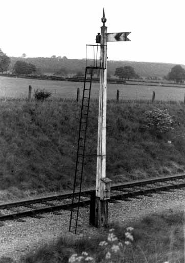
| Cranmore down fixed distant, note the cutout behind arm, as this was at one time a working signal. (1976) |
 |
 |
 |
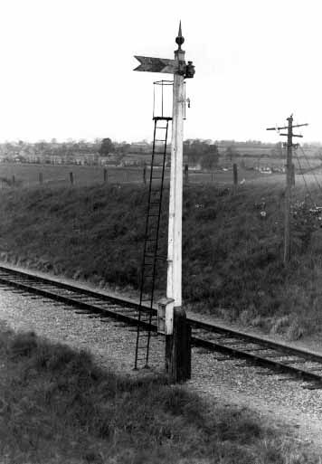
(right, and below) Mells Road up fixed distant, 1978.
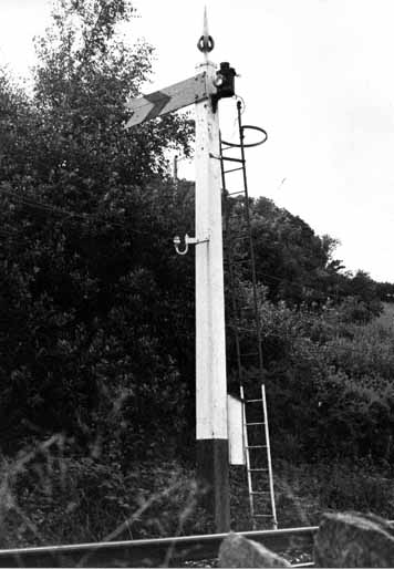
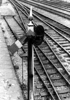
A useful way of calculating the height of signals is by counting the rungs of the ladder. The rungs are 10¼" apart. The stiles are 10" apart, and the rungs are ½" diameter. This post is 27'6" high. Posts over 26' high were fitted with 5' long arms.
Note the short height of the telegraph poles.
|
 |
 |
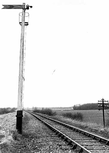
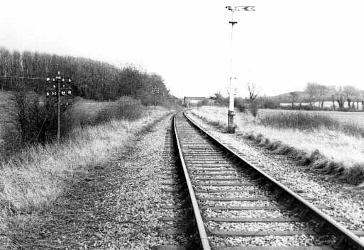
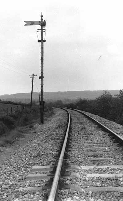
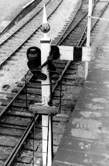
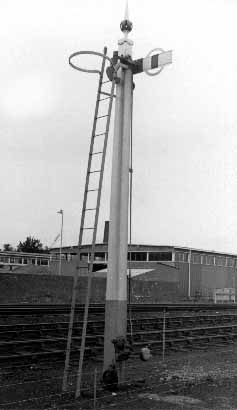
Lostwithiel up branch distant, 1978. This signal is 21' high, and therefore has a 4' arm. Unlike the other signals here, this one is complete, and is connected to the lamp out indicator. The battery box at the base is also complete. The battery supplied power to the 'lamp out' indicator in the signal box. This would represent one wire to the box, hence the single insulator on the post. The lamp is mounted on a small bracket. The ladder incorporates a handhold at the top. The other stile is attached to the post. |
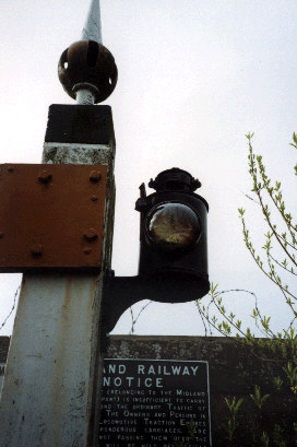
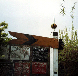
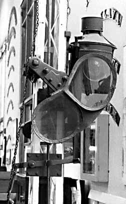
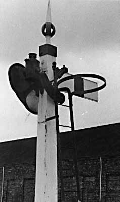
| Fishtailed fixed distant at Winchcombe Museum. Note here that the finial only goes round 2 sides of the post. I am advised these were introduced to go onto concrete posts. You could not just shave off pieces to fit the finial on. The close up shows the lamp bracket. Also note the lens on the lamp casing. Remember that the oil lamp slips inside the casing. |
 |
 |
 |
Just for completeness, a steel-post fixed distant, in full working glory. Again, one wire goes to the telegraph pole. A battery box is near the base. Witham junction for Wells (Somerset), up branch. |
Worked signals
 |
Newbury Bay Starter, 14 July 1977. This had a shortened arm, less than the standard 4', because of limited clearance against the retaining wall. The 'backlight blinder' obscured the rear hole in the lamp casing, so the signalman could see the signal was 'off'.
Part of the stage is missing. This signal was replaced the following year under the MAS scheme in the area. |
 |
 |
| Inside the old Swindon Museum. A separate arm and spectacle plate, provided where the arm was over 26' high, the lampman here had winding gear. Only the lineman had to climb to the top to oil the bearing. |
 |
 |
A ringed siding arm at Shrewsbury, with a non-standard narrow arm
 |
Aberystwyth, from the rear
 |
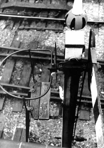
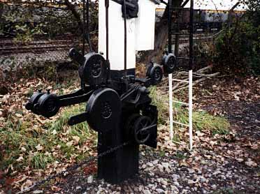
Balance weights and pulleys
|
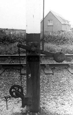
Close up of a balance weight and its pivot. In this case, the signal wire is coming from the left. Hence the lever is apparently upside down. Ffestiniog station up home, 11 September 1978. |
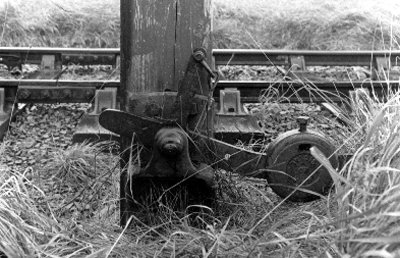
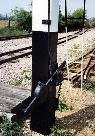
Balance weight and lever of a different pattern. Here the signal wire starts as a chain and goes round a wheel. The bracket is screwed to the post. The balance weight can slide along the lever arm, to give the right amount of return to the arm. Dyffryn Arduddwy crossing up home, 12 September 1978.
 |
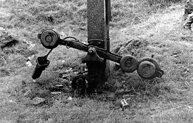
Three-quarter view of a similar lever and bracket arrangement, this time on the preserved narrow gauge railway at Toddington.
|
 |
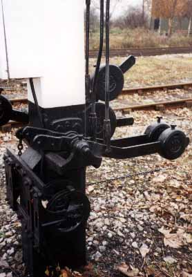
A slotted lever and balance arrangement on a concrete post. Here the signal itself is not directly connected to the pull wires but is attached to the weight on the left. There are two levers on the right, one is connected to the signal box, the other lever to a crossing box further out. The two pulleys are for the pull wires. Hanging on the left is the electric detection (slot off) for the box – it should be mounted on the post but this signal is derelict. Blaenau Ffestiniog outer home, 11 September 1978. |
 |
Front and rear views of an atypical arrangement of holding the pulleys at Didcot Railway Centre.
 |
 |
Sketch of a balance lever, made from 2½" x ⅝" strip. The weight is 7½" diameter x 2½" thick. I made the levers out of nickel strip, with slices of brass bar with slits cut in to slot over the lever. Soldered on when I had the weight in the right place. |
Bracket signals
 |
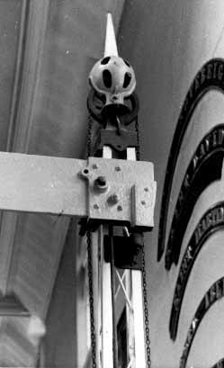
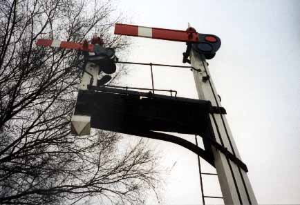
I have increased this picture's brightness to accentuate the cranks that operate the arms. This is a detail I could never find when I looked at published sources. Note the separate cranks used to get the movement up to the arm.
Bewdley down home, Severn Valley |
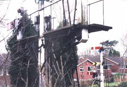
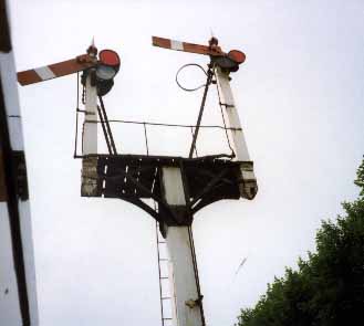
Below is an older style of bracket, using a counterbalance arm each side.
|
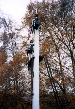
Against the light, so we can't see what is going on. Arley down home, Severn Valley.
 |
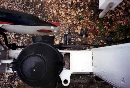
I hope you can just about make out how the pivot is fixed on to the underside of the deck, Didcot Railway Centre.
 |
Long shot of the bracket at Didcot
 |
Showing how the pivot is fixed to the bracket. This signal has been cobbled together from various components, but I am sure the bracket itself is Western.
Bala Lake Railway
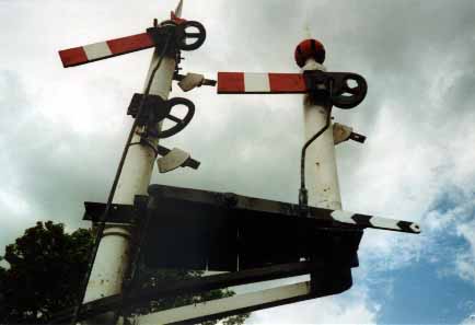 |
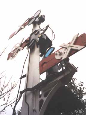
Overhead shot of a different sort of bracket, but similar method of making the arm work. (I did have permission to be up the signal.) Didcot Railway Centre.
 |
The same signal from ground level, showing the counterbalance arm.
 |
|