| Section Page | Previous Page | Next Page |
AA7 Brake Van
|
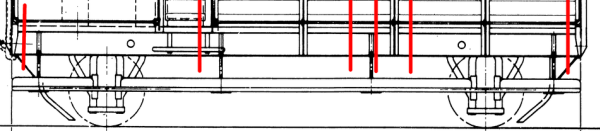
| The underframe was tackled first. The floor/solebar units needed extensive cutting, ending up with six parts. After 2mm was removed from the ends of the units, cuts were made 28mm from each end (separating the axle guard sections). A cut was made next to one of the stepboard supports, and then another 6mm from this cut. The sketch shows the approximate location where cuts are required in the floor/solebar units.
As the stepboard support is offset towards the verandah it is necessary to decide which end will be the verandah end at this stage. The kit instructions suggest filing a notch in the edge of the floor 10mm from the verandah end. This notch can later be drilled out to 1mm to locate the brake handle. On the AA7 van the notch should be 8mm from the end. This resulted in six sections that can be joined to remake the two half floors, a total of 62mm long, with the correct wheelbase and with a single stepboard support offset from centre. At this stage holes were drilled in the solebars to represent the horse hook holes. When reconstructing the underframe, care needs to be taken to ensure that the solebars are straight, and that when the wheels are inserted the axles will be parallel to each other and perpendicular to the solebars. Where the various sections are rejoined, some strengthening will be required. A false floor, 62 x 28mm, was cut from 10 thou plasticard. Unfortunately it was discovered later in the construction that the false floor got in the way of the sides, so the false floor should be smaller (so that it fits inside the cabin). In order to ensure that the underframe was square, with everything lined up correctly, a template was made from some 2mm thick mount board. A 62 x 28mm hole was cut in the mount board, and pencil lines drawn to indicate where the wheel centres should be, the centre lines were also marked. As the template is 2mm thick, the false floor, and the underframe parts, can be located within the hole, this will highlight where any fettling is required. Before assembling the underframe and false floor, brass pinpoint bearings were inserted into the back of the axle boxes. With the parts located in the template the wheels were temporarily inserted in their place, this helped to ensure that the axles are actually square and the wheels turn freely. |
 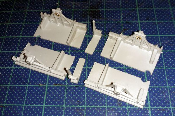 The six underframe parts, after cutting but before reassembly 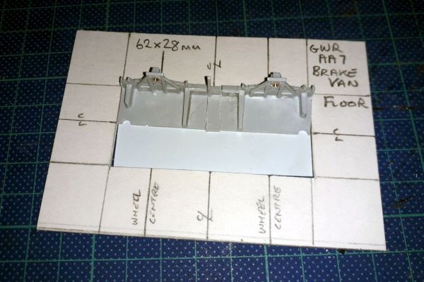 One side of the underframe, and false floor, in the cardboard template 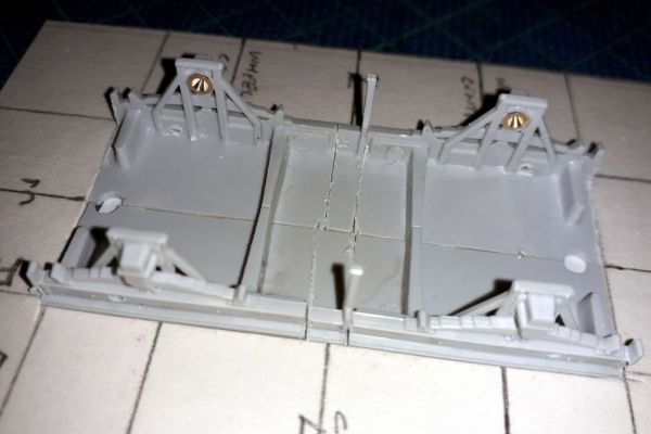 Ready for glueing, the underframe located in the cardboard template |
Some pieces of 20 thou plasticard were added between the ribs on the underside of the floor to improve the models strength. The clasp brake parts fit between the ribs behind the axle guards, and so the strengthening pieces must not interfere with their location.
The clasp brake parts are designed to fit between the ribs either side of each wheel, with the two pips hard against the solebars. Some fettling was required to make these a good fit, while still allowing the wheels to turn freely. The brake part was worked on for a wheel, and then assembled dry, and the wheels inserted to see what further fettling was needed.
The tiebars between the axle boxes were then replaced with brass wire secured with superglue. Before fitting the wire was filed to a slightly flat profile, better representing the profile of the prototype parts.
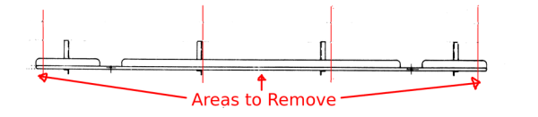
| The stepboards are quite fragile, and the required alterations will weaken them further: pieces of thin plasticard can be stuck to the bottom surfaces to strengthen them. The length of the stepboards needs to be reduced to 64mm, the recesses will need to line up with the axle boxes and one of the supports will need to line up with the corresponding support on the underframe. The sketch shows the approximate areas that need removing.
Rejoining the stepboards was fiddly. An offcut of 2mm mount board was used to provide a straight edge to align the stepboard parts while glueing. If the van is to represent the original condition, new stepboards could be fashioned from suitably sized L section. |
 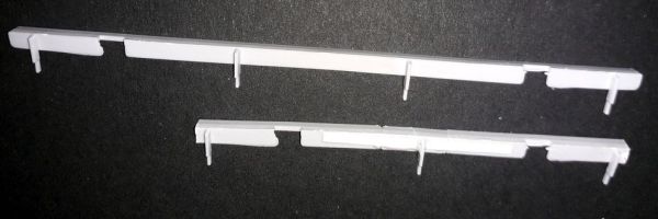 Step boards: as supplied (top) and as modified (bottom) |
Cabin sides
| The overall length of the cabin sides needs reducing to 45mm, but there are still three stanchions on each cabin side. This means that the panels between the stepboards as supplied (top) and as modified (bottom) stanchions need to be reduced. The cuts should be near the stanchions, but not right against them, careful alignment will be needed to ensure that the planking lines up. Care is needed to minimise any damage to the moulded handrails, alternatively these could be removed and replaced with wire. | 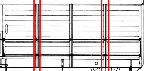 |
The sides are divided into five sections (A – E) in the sketch. The centres of the stanchions will need to be at 12mm, 22mm, and 31mm from the verandah end of the cabin.
The reconstruction involves trimming parts A and E to length, then adding the stanchions B and D. Part C is then trimmed to fit between the other parts. A piece of plasticard can be secured behind parts A and E, thus establishing the correct length of the side and strengthening the rebuilt side.
| Another template was made out of 2mm mount board, this time sized 45 x 25.5mm. The position of the vertical stanchions was marked on the cardboard. This template aided the trimming and fettling of the parts of the sides by holding the pieces square, and getting the stanchions correctly spaced. | 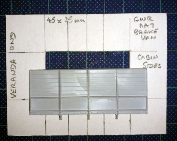 Cardboard template for reassembling the sides. Note how much smaller the aperture is compared with a cabin side as supplied |
| The cabin sides will be quite noticeable on the finished model, so getting as good a fit of the five parts as possible is very desirable. Carefully measuring where the cuts will be made, and much fettling with a small file, allowed the sides to be fitted together while maintaining the desired overall length of the side.
The sides have ridges moulded on the back that locate against the train end, cabin end and floor. On the altered sides the ridges between the end parts are 40mm apart. A piece of plasticard 40 x 20mm can be stuck against the inside face of the ridges which will make the sides the correct length. The floor ridge will also help to verticaly align the side parts. The remaining side parts can then be assembled using the plasticard as a strengthener. |
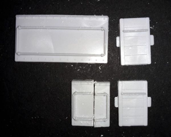
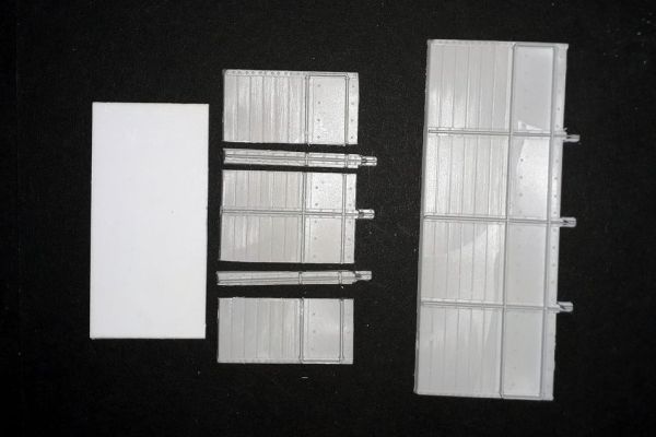 Plasticard backing to altered cabin side, a sectioned cabin side, and an unaltered cabin side as supplied in the kit. Note just how much shorter the modified side is compared with the original 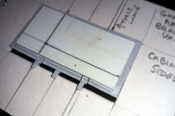 The back of a modified side showing the plastic backing against the alignment ridges. (Ignore the pencil marks on the plastic support piece.) |
| At this point a dry run assembly was attempted. It was discovered that the floor was too thick because of the plasticard sheet. After trimming the false floor back the train end and a modified side were located on the floor, and found to be a good fit. The other side was then modified, again a dry assembly was done to check the fit.
The modified sides were then fixed, along with the cabin outer end and cabin inner end, to form the cabin. Due to the plasticard false floor the bottom of the cabin end needed to be filed slightly. |
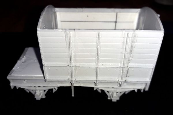 The cabin assembled on the underframe |
Verandah sides
| The verandah doors have a lug on each side, which locates in a notch in the cabin end. The two doors and the verandah end were fitted next.
The actual verandah sides need to be significantly reduced in length, the gap between the verandah end and the doors is approximately 9.5mm. In the Model Railway Constructor article it was suggested that end part of the handrail be pared off the side to be later reattached. However in this build the centre section of the verandah sides were simply cut out, leaving the two ends parts. The parts of the verandah sides were filed until they fitted between the verandah end and the doors. Once they fitted they were attached, the solvent helping to ensure a good fit. |
 Top: unmodified veranda side and door. Bottom: the altered veranda side and door. Note the amount of shortening required |
Verandah fittings
There should be planks across the verandah floor. These were omitted.
The sand boxes were assembled, and after leaving to dry the bases were filed smooth. These are attached, using superglue, in the corners between the verandah end and sides, after painting the verandah interior.
The brake standard is very fragile, when attempting to remove the part from the sprue the handle part broke. The brake standard was glued into to the 1mm hole drilled in the floor when preparing the underframe.
Roof
The roof proved quite tricky, and as it is the most visible part of the model (at least when viewed on a layout) it is important that it looks right and fits well. In the end I needed three attempts to model the roof.
The first idea for modelling the roof, cutting down the one supplied in the kit, did not work because of inaccuracy in making the cuts. The end of the roof was cut off, and another cut further inboard. The two outer sections were then joined. This attempt was abandoned, but the parts kept.
A second attempt was made by cutting a new roof from 20 thou plasticard. This was placed on a mug of appropriate diameter, secured with elastic bands. Very hot water was then poured into the cup. The first attempt failed, because the bands were not tight enough. Fortunately styrene sheet can be heated again to soften it. The second attempt, using masking tape to hold the plastic, worked better but it was still not as close a fit as would have been desirable.
After fitting the plain plasticard roof, it just didn't look right. The length, width and curve were good, sometimes the eye can detect things that are wrong even if the dimensions are fine. At this point it was decided to revert to the original plan. However, the roof support hoop at the verandah end broke while removing the roof. A new hoop had to be fashioned. Some more fettling allowed the parts from the roof supplied in the kit to be used.
Final assembly and details
After the main assembly was completed the stepboards and detail parts were attached. The stepboards should locate against the front of the axleboxes just above the seam.
The foot steps are fitted to the solebars below the side doors.
Etched brass coupling hooks were worked through the slots in the buffer beams until a sliding fit was achieved, before the ends were fitted to the floor. The fitting was undertaken once the main construction was completed.
The buffers from the kit were fitted to the ends. Cast white metal vacuum pipes were attached with superglue.
The roof was left unattached until after painting.
Painting and finishing
The model was painted with Humbrol 32 (Dark Grey) acrylic paint, this is a bit darker than the standard GWR grey. A yellow brown colour was mixed from Daler Rowney artists acrylics (approx 3 parts Yellow Ochre, 2 parts Light Brown and 1 part black) to represent an unpainted wood colour which was applied to the verandah floor.
The handrails were picked out in white, the Daler Rowney acrylics give a heavily matt finish.
At some point in GWR history vacuum brake pipes were painted red on braked wagons and black on piped wagons, this may have been late 30s or WW2 period. However, the colour adds some interest to the model. Black from the Daler Rowney acrylics was used to paint the vacuum pipes.
HMRS pressfix transfers were used for lettering the brake van in the large (25") goods wagon livery. According to the July 1976 Model Railway Constructor article, the painted depot allocations were not introduced until the medium (16") livery was introduced.
The HMRS transfer sheet I had separated the wrong way. The intended backing sheet removed easily, but the card sheet (printed with notes) did not. Consequently, it was difficult to see where the required transfers were on the sheet, not helped by the white colour of the backing sheet. However, the transfers were easier to use than expected. I did find lining up the number quite difficult, even though the numbers are not straight they don't look too bad.
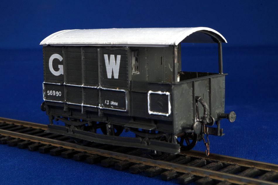
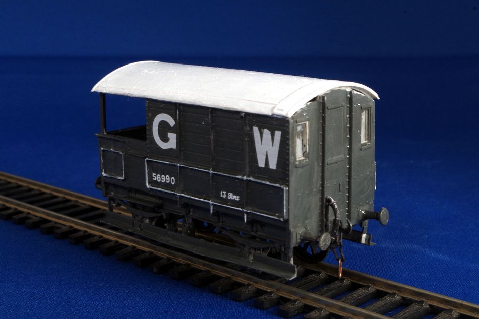
The brake van was given the identity 56990.
Conclusion
This would be a challenging project for an absolute novice, but it is not too difficult and for a modeller who has constructed a number of plastic kits could be a valuable introduction to kit-bashing. The ability to cut and fit plastic parts is the most important skill required. The original design of the ex-Ratio kit allows the modifications to be kept to a minimum.
I enjoyed producing this relatively unusual brake van, I improved my own skills, and I would certainly recommend the subject for other modellers to attempt. The project was definitely worthwhile.
| Section Page | Previous Page | Next Page |