| Section Page | Previous Page | Next Page |
Layout of Stephenson gear on a Churchward standard 2-cylinder locomotiveby Jim Champ
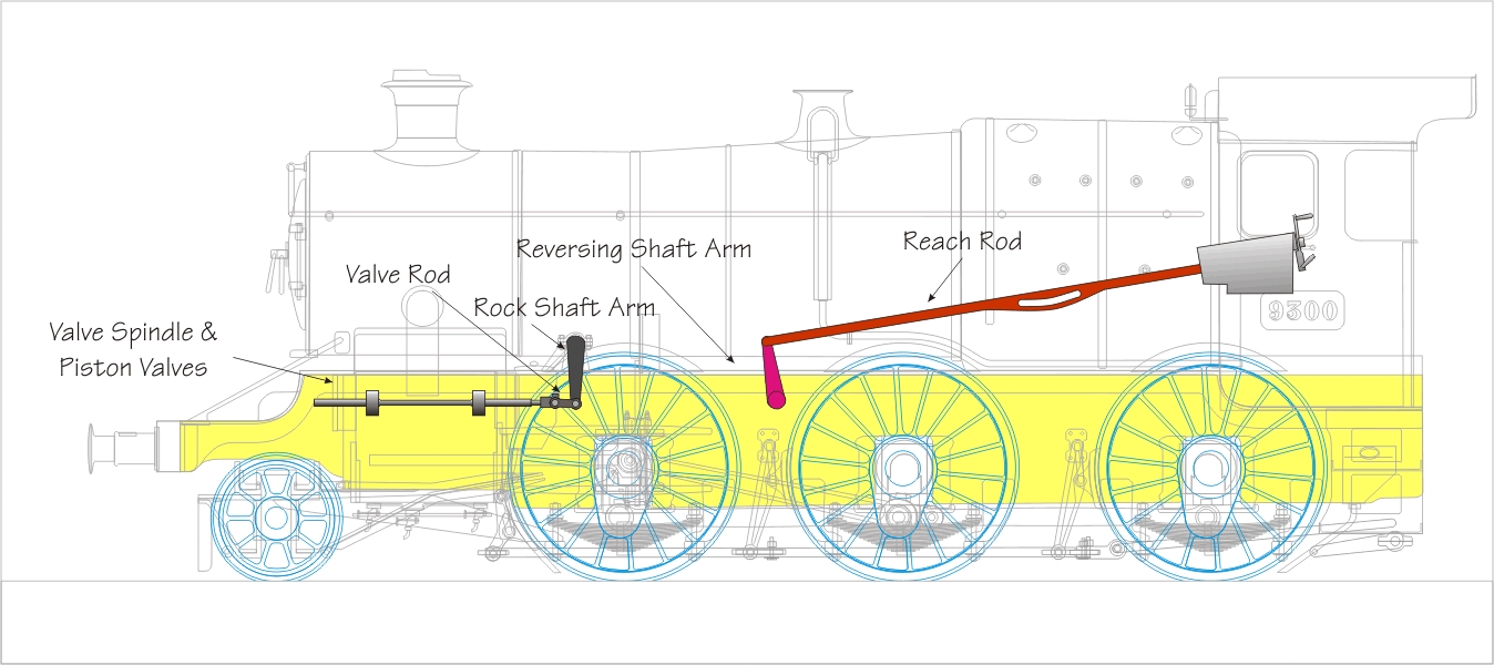
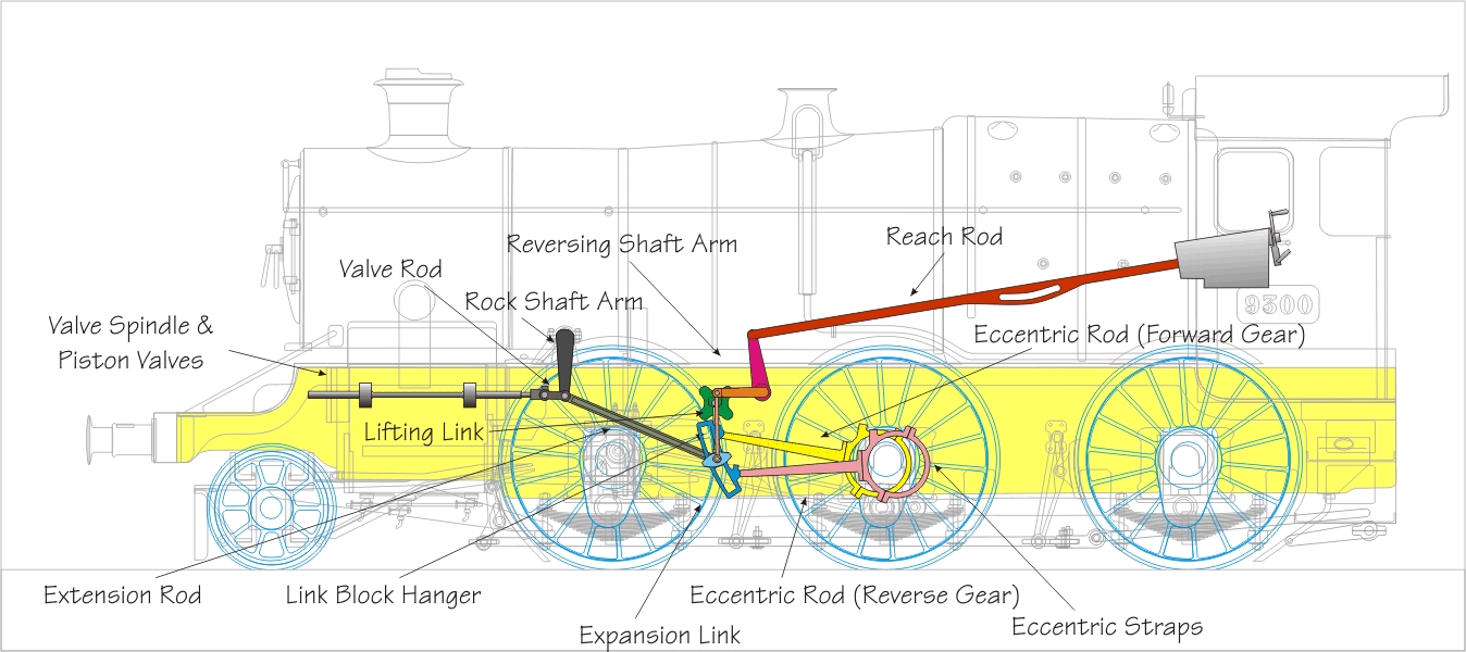
1 Outside the framesThis shows the reach rod and the piston valve and external rock arm. Both are connected to transverse rods which transfer movement to and from the components inside the frames. The reversing shaft goes across the frames and activates both sets of valve gear, (and there is no reach rod on the left hand side of course) but the rock shafts and rock arm assemblies are on both sides of the locomotive and independant of each other.
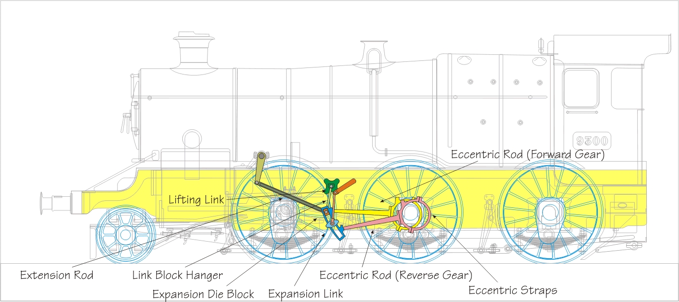
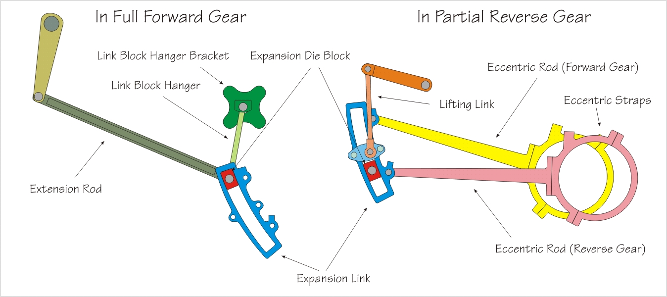
2 Between the framesFull forward gear The gear is controlled by the relative position of the expansion link and the expansion die block (also called the link block).
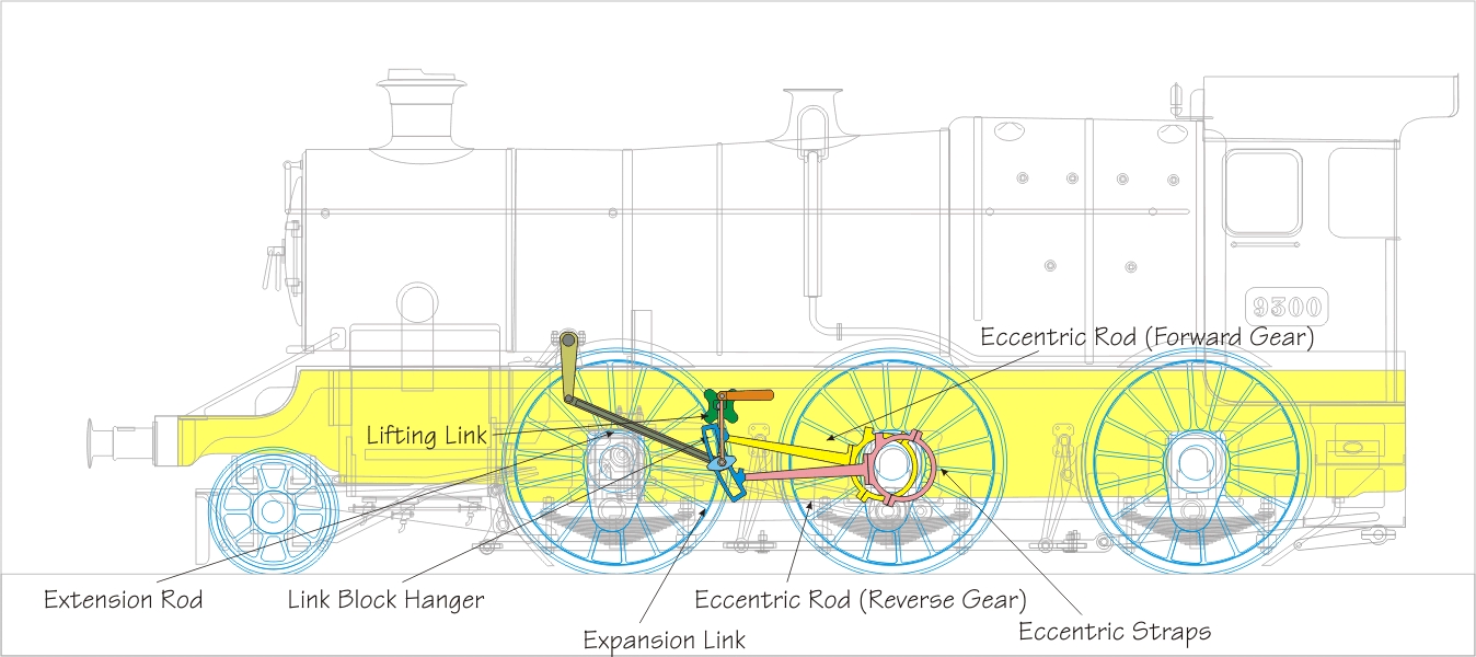
Mid gear In mid gear the die block is in the centre of the expansion link, and experiences much less horizontal movement so insufficient motion is transferred to the extension rod to open the valves to admit steam.
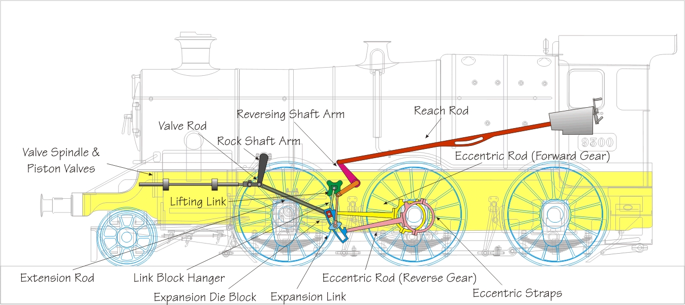
3 All the components togetherFull forward gear
Mid gear
4 The components in detail
Further readingThere are numerous sources for descriptions of the functioning of Stephenson's Link Motion. For a practical introduction to the motion (and almost everything else) on GWR Locomotives "GWR Two Cylinder Piston Valve Steam Locomotives" by E.J. Nutty is a valuable text and includes an excellent isometric drawing showing the parts in detail. For some more sophisticated understanding of valve gears I suggest Don Ashton's Steam Locomotive Valve gears site, especially in this context the page on Stephenson's gear.
© Jim Champ |
| Section Page | Previous Page | Next Page |