| Section Page | Previous Page | Next Page |
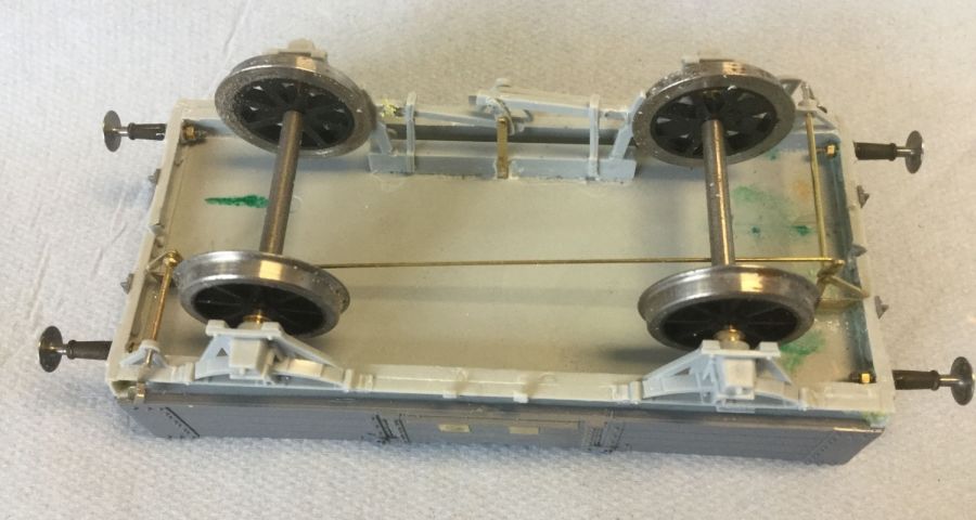
A Beginner's Guide to GWR wagon brakesby Jim Champ (with some modeller's notes, primarily for 4mm kitbuilders) Introduction GWR wagon brakes 1 are an immensely complicated subject. The GWR – typically – tended to go its own way on brakes to some extent, and it seems there's always another layer of the onion inside to understand. This piece is only intended to provide a broad-brush introduction to the topic and contains scandalous over simplification, errors and omissions. For simplicity it will only cover the most common arrangements found on standard 9' and 10' wheelbase wagons during the 20th century – opens and vans. When one comes to long-wheelbase vehicles, bogie stock and the many special purpose designs then all sorts of complications appear. There are also almost infinite numbers of oddities, exceptions and peculiarities. There are many excellent references in and out of print for those who wish to cover the topic in detail 2, but hopefully this article will be enough to gain a basic understanding of the topic and to avoid a few of the errors that can be made assembling kits. The sketches here are simplified. When you look at a preserved wagon, or clear photographs, especially of a wagon upside down 3, there is an amazing multiplicity of pieces of bent metal. Almost any component of any size was fitted with a safety strap or bracket so in the event of a fastening failure or a breakage it couldn't fall off and damage or derail the train. There were all sorts of adjustments, manual and semi-automatic, to adjust the equipment to allow for wear or whatever much of this is either omitted or simplified in ready-to-run and model kits. Dimensional inaccuracies, too, are not uncommon. Because many brake arrangements were somewhat asymmetrical I am going to refer to primary and secondary sides of the wagon. The primary side is the side with brake shoes if brakes are only fitted on one side, and on wagons with shoes on both sides is the one where the brake shaft rotates clockwise to apply the brakes. Board of Trade rulings on brakes The Board of Trade issued rulings on brakes in 1911. The first of these required that brakes had to be operable from either side of the vehicle and that brake levers had to be provided at the right-hand side. This is known as the 'right-hand either side' (RHES) rule.
Lever brakes
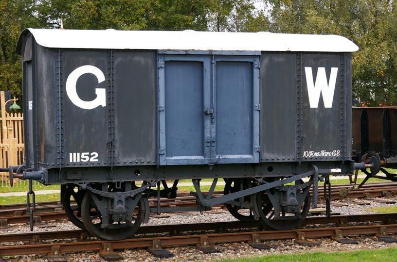
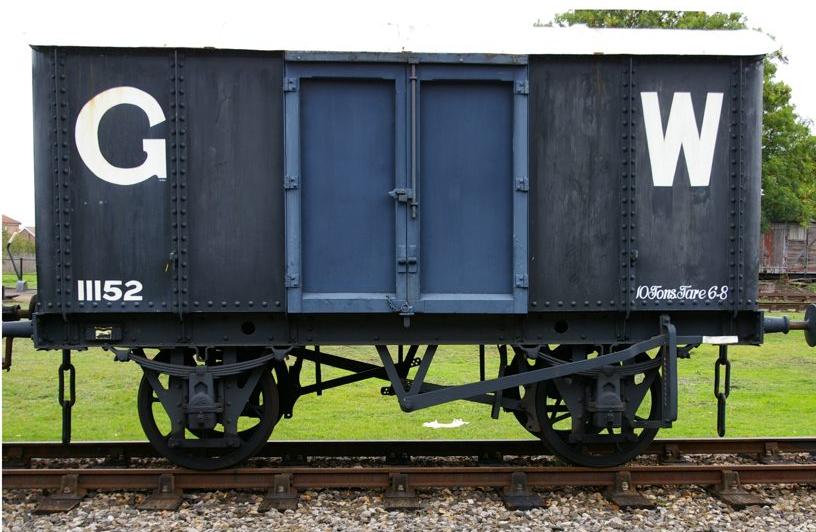
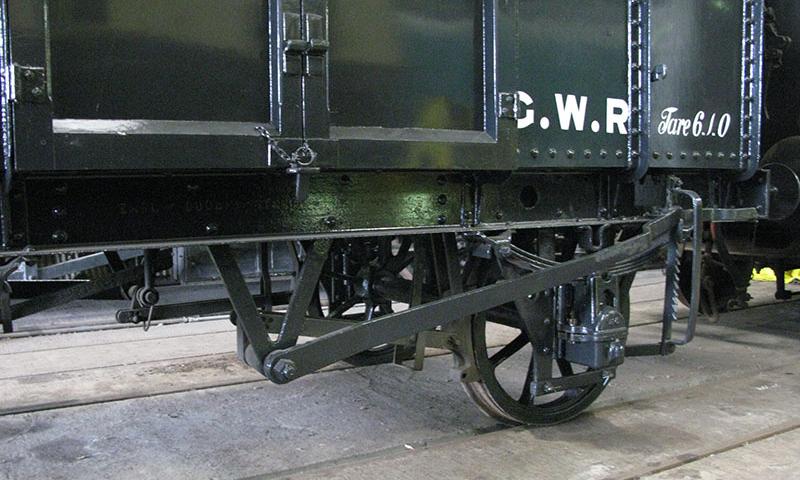
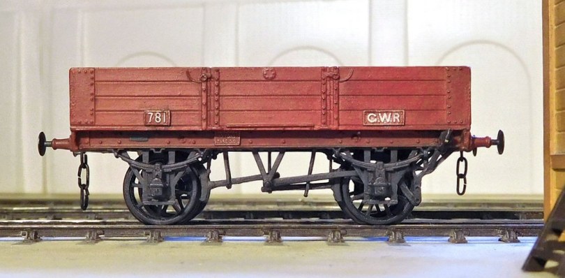
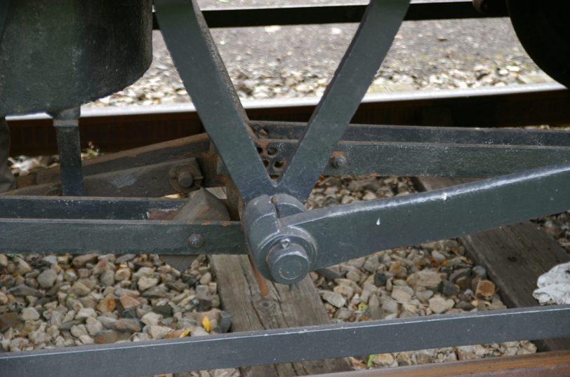
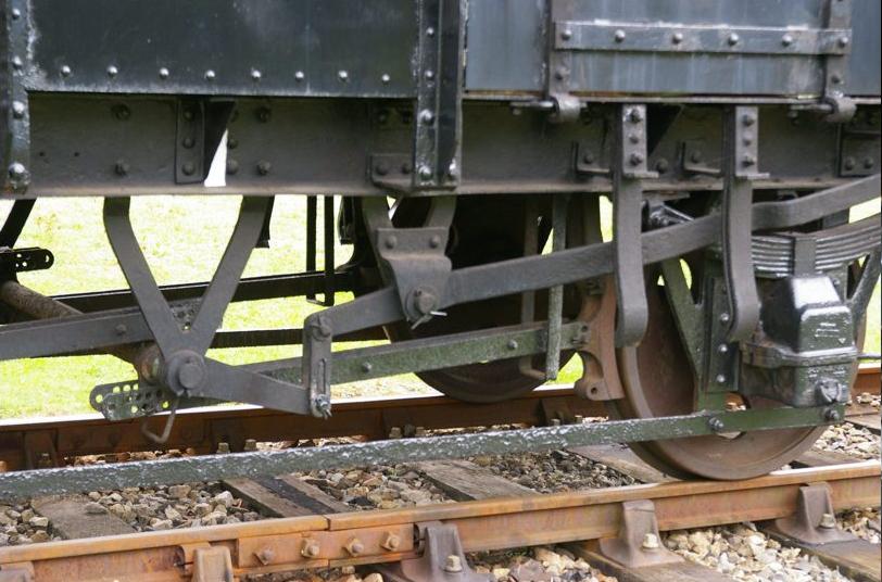
The principle is simple. The system was built around the V hanger. This carried a short transverse shaft. The brake lever was attached to one end of this and it went through the V hanger and carried a pair of short arms. A simple vertical support (or on some non-GWR wagons another V hanger) supported the inner end of the shaft. The arms were connected to push rods, which ran through prominent safety straps and onto the centre of the brake shoe, which was held in position vertically by another support up to the solebar. When the lever is pulled down the shaft rotates clockwise and the push rods apply the brake shoes to the wheel rim 4. To comply with this brake ruling, surviving wagons with lever brakes on only one side had to have an extra brake applied to the secondary side. Oddly this was often a single brake block – an arrangement that can be seen on photos from WWII and post-war. Models with single-sided lever brakes, Ratio Iron Minks for example, need to have an extra brake fitted on the other side for post-1939. A hunt in the spares box for unused components on Cooper-Craft sprues ought to provide reasonable raw material. The Iron Mink is probably the most obvious GWR vehicle to look at for lever brakes: there are good official photos of the "Salvage: Save for Victory" Iron Minks from WWII which show lever brakes well 5. One of these (47305) has the single extra brake shoe on one side, as does the preserved Iron Mink at the Great Western Society shown below. The additional single shoe brake was a late modification to comply with the right-hand either-side independent BoT regulations, i.e. release only on the side from which it was set. A few Iron Minks received these in 1924, but most were fitted from 1927 up to WWII.
When a wagon is fitted with lever brakes on both sides then both sides of the wagon will have exactly the same arrangement, the two sets of brake shoes operate quite independently and you can't really identify a primary and secondary side. Other common types with lever brakes were diagrams 6 N6 (single-sided) & N33 (double-sided) loco coal, O21 4-plank Opens 7 and W1 cattle wagons. Independent lever brakes of various configurations were also found on special-purpose stock where design considerations made either side brakes impractical. The GWR seems to have had very few vacuum-fitted wagons with lever brakes – early vacuum-fitted wagons seem to have had arrangements similar to coaching stock, which is another tale. Various 19th century prototypes modelled in the David Geen range had these brakes. Of later wagons built in any numbers the last diagram of Macaw B, J28, had independent lever brakes as did most other larger post 1939 wagons – clearly the extra complexity of either side brakes was considered unnecessary on these special-purpose vehicles 8.
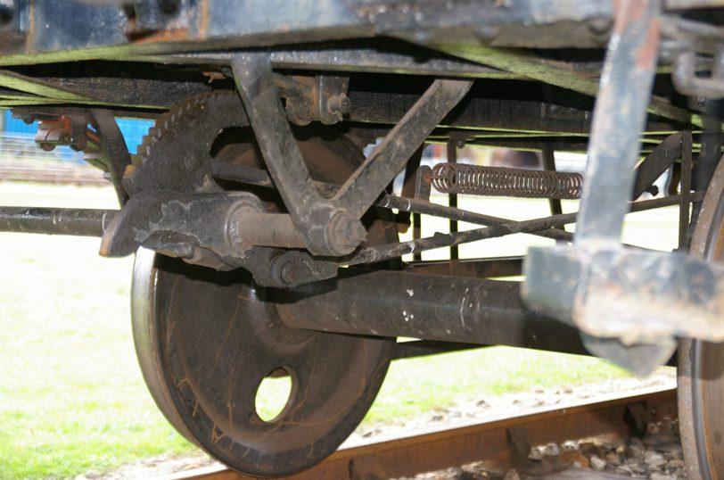
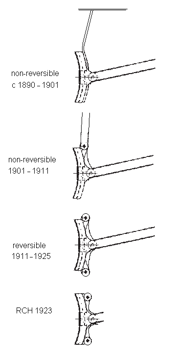
Either-side brakes At the end of the 19th century, "either-side" brakes started to come into use. The first used by the GWR, which doesn't seem to have been very satisfactory, was the "Thomas" brake 9. Operation was by turning a crank each side of the wagon – clockwise one side, anticlockwise the other 10. It doesn't sound very easy for the shunter running alongside, and it was never used in volume production. Dean-Churchward brakes The Thomas brake was superseded by the Dean-Churchward style brake, which used a short lever with a ratchet, which was pulled down to put the brake on, and lifted to release. Modern railway historians 11 divide the Dean-Churchward brakes into three basic types, DCI, DCII and DCIII. DCI
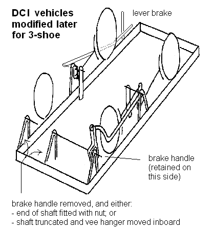
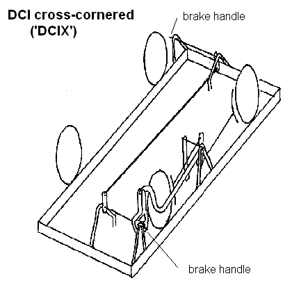
DCI brakes seem only to have been used with unfitted wagons, and only with a single set of brake shoes on the same side as the swan necked lever. Thus on the secondary side of the wagon the lever would be on the left-hand end and there would be no other gear. From the mid-1920s, consideration had to be given to the large number of wagons needed to be modified when the right-hand only regulations came into force in 1939. These regulations mandated that the brake lever was always on the right-hand side of the wagon. It should be noted however, given there were still some surviving wagons with both levers at the same end after WWII, complete compliance was never achieved. Of those DCI-fitted wagons that were modified to comply, there were two options:
Amongst the more common types with DCI brakes were N13 loco coal, O5 4-plank and O3/O4 5-plank opens, and V4/V5 vans. (The V4 however was an oddity, being rebuilt almost immediately after introduction with an 8-shoe clasp brake arrangement.) When assembling Cooper-Craft kits – which are the most common ones with DCI brakes – you need to consider brakes carefully. The kits omit the "Swan neck" lever – to me a significant omission – and include sets of push rods and brake shoes arranged for both lever brakes and DC brakes, so its easy to pick the wrong set of brake blocks when assembling their models. There are V hangers for all sorts of options, the majority of which need to be removed. Make sure that you pick the correct shoe/push rod assemblies for the brake style you have selected, and only remove the unwanted V hangers. There are various etches available of DCI brake gear which include the Swan neck lever if its absence (or the rest of the Cooper-Craft brake gear) offends you. Note that the Swan neck lever goes outside the brake blocks and push rods. If you're modelling WWII or after then you should assemble all or at least the vast majority as DCIX. Another nice tweak is to use some round microstrip to add the transverse rod between the brake levers on DCI: this is surprisingly prominent – at least if you aren't using Hornby couplings!
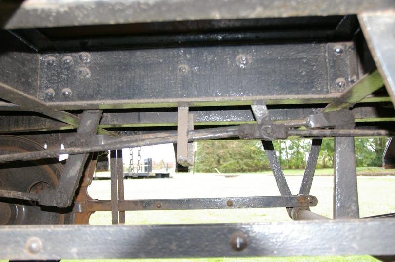
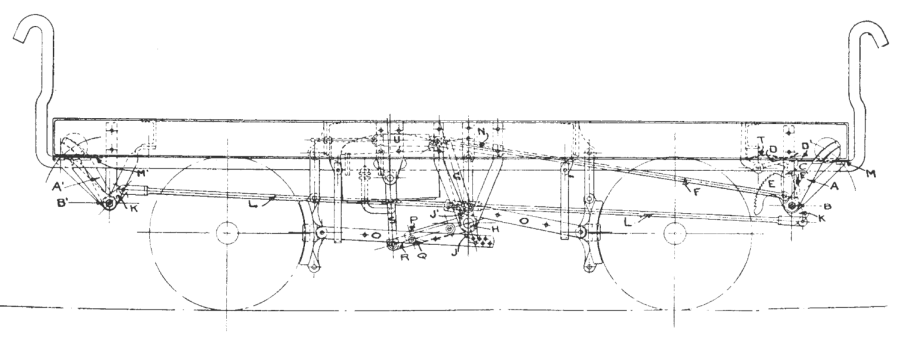
DCIIDCII brakes used the same style of lever at one end of the wagon, but didn't use the long swan necked lever. They typically had a pair of brake shoes on each side of the wagon, with a transverse shaft across the wagon between V hangers to link them. The gear seems to have been worked out for vacuum fitted wagons, and was principally used on those and on longer unfitted wagons where extra brake power was required and the wheel spacing was greater. Instead of the swan neck lever there was a long arm on the transverse shaft which went upwards to around solebar height. This arm connected to a rod leading, probably via an intermediate lever13, to a transverse shaft across the wagon carrying the brake levers. A rather differently shaped ratchet was located next to the arm on this shaft13. Because both sets of brake shoes were permanently linked the brake lever was at the right hand end on the primary side, and the left-hand end on the secondary side. The centre axle rotates anti-clockwise on the primary side when the lever is pulled down so the arms and pushrods are oriented the same way as on a standard lever brake, and the opposite way to the DCI. However the brake assemblies are mirror images of each other, not identical, as they were when there were individual lever brakes each side, as they must be because both sets of brakes are operated by the same shaft running across the wagon, so on the secondary side the centre axle rotates clockwise. If the wagon was vacuum-fitted – and most DCII wagons were – then the vacuum cylinder was situated to the left of the central transverse shaft looking at the wagon from the primary side. There was an arm from the transverse shaft which connected to the rod from the vacuum piston. This had a fork or slot arrangement to act as a "lost motion" clutch so that applying the handbrake did not affect the vacuum piston. Similarly there was another slot/fork lost motion clutch arrangement, plus a return spring, where the rod to the hand brakes met the arm on the transverse shaft. This ensured that when the vacuum brake was applied the hand levers didn't move: that would also result in the ratchet taking effect – which would be very undesirable indeed! From 1939 mainstream DCII wagons would need to be converted to cross-cornered brakes, but this was not a complex operation. I'm not sure that for our purposes DCII converted and DCIII are distinguishable. DCII vacuum fitted brakes featured on, amongst others, some N2 & N4 20T Loco Coal, some O3 opens, O9 opens, (most) V3 Vans, V4, V8 and V9 Vans and W5 cattle wagons. The 4mm Parkside-Dundas V11 Mink D has a variation of DCII brakes with clasp brakes (8 shoes, one on each side of each wheel) and brake levers near the centre of the wagon. Post war photos of V11 all show the wagons (some in departmental use) with DCIII brakes and 4 shoes. Dialogues on GWR e-list 15 state that earlier production had the DCII, converted later to standard DCIII, and later batches had DCIII from new. Unfitted DCII brakes were found on some N2 minerals, O9 opens and O12/13 end tipping china clay wagons, the latter presumably because all the brake gear could be kept away from the tipping end. They were also used on J14 and J21 Macaw B Bogie flat wagons, but as the brake levers were located in the centre of the wagon, not at either end, the identification of them as DCII rather than DCIII is to my mind somewhat nominal!
DCIII
To make a sweeping generalisation DCIII brakes were replaced by Morton brakes soon after the grouping on new built wagons in the common pool, but were used somewhat longer on builds of "Not Common User" and Departmental wagons until its use for new builds was finally abandoned in 1939 17. DCIII vacuum-fitted diagrams included O9, O15, O22, and some O36 Opens, V7, V12, V22 vans and W8 cattle wagons. Parkside-Dundas Mink G and S8 Bloater Vans have long wheelbase varieties of DCIII brakes. Unfitted DCIII brakes could be found on O11, O14, O18 and some O22 opens, the long-wheelbase Open C up to O34, quite a few loco coal and minerals such as N19, N20, N21, N23, N27, N31, and V12, V13, V14 vans plus the long wheelbase V22 vans.
Morton brakes
In order for the levers to act independently, as they had to, this meant a multiplicity of lost-motion clutches, especially on vacuum-fitted wagons. The DC arrangement was lighter and simpler. On the primary side the hand brake had a simple lost motion clutch in line with the lever and shaft, which for modelling purposes is almost invisible. On the secondary side the arrangement is more complicated because the force from the lever would attempt to rotate the brake shaft in the wrong direction. The Morton design uses two adjacent cams to provide both the clutch and the reversal of rotation. Examples included the various Conflats, N30 10 ton Loco Coal, N24, and most of the later 20/21T end door fitted mineral wagons, most O22, O23 opens onwards, and V18, V21, V23 and later vans. The Parkside-Dundas Fruit D has Morton style fitted brakes, and the Cambrian N30 Loco Coal unfitted, as do the Ratio Open O29 and Mink V23.
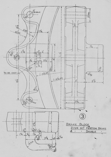
Brakeshoes
Conclusion It needs to be stressed that this is a very simplified introduction to a complicated topic, but if you now know what a DCII brake is and can pick out the most suitable choice of components from a kit for your model, then it will have met its limited aims. Perhaps the main thing to remember is that there was an exception for everything, and every statement in this article should be so qualified. A single example will suffice – on the GWR Modelling e-list18 there's a report of an Iron Mink that was first converted to DCI brakes, and then, when a cross cornered brake lever was required, had a single shoe lever brake added on the secondary side and the DCI lever removed on that side!
Further reading Subsequent to the production of this page, Brian Morgan has issued a series of 4mm scale etches to cover many GWR wagon brakes. The very comprehensive instructions contain good illustrations of the brake varieties discussed above.
Footnotes 1 The main reference throughout is "GWR Goods Wagons A Historical Survey", Atkins, Beard & Tourret, 2013, OPC, ISBN 978 86093 657 2 (ABT). This is, I think the 4th Edition but one version or another is almost essential if your interest extends beyond the level of this article). I've also learned a lot from various contributors on line on the GWR e-list and GWR Modelling list on Yahoo groups, notably John Greenough and John Lewis, who have also reviewed this document. Mistakes, appalling over-simplifications and misunderstandings are of course my own. 2 Beyond "GWR Goods Wagons" there are too many to list, but anything with Atkins, Hyde, Beard, Tourret or Russell in the author's name field is probably a good bet. Don't forget your local Library Service: the Surrey County Council Library Service, for instance, has copies of the three volumes of wagon photos by Russell and of the invaluable "GWR Goods Wagons". 3 The 4mm wagon Part One, p34, Geoff Kent, 1991, Wild Swan Publications, ISBN 1 874103 03 8 4 There's a particularly clear photo on p34 of "Great Western Wagons Appendix", JH Russell, 1974, Oxford Publishing Co, ISBN 0 902888 03 X, (RWA) showing an early small Cattle wagon. 5 Excellent photos in Fig 52 and 53 in Freight Wagons and Loads in Service on the Great Western Railway and British Rail, Western Region, J H Russell, 2000 Edition, OPC, ISBN 0 86093 155 2. 6 GWR Wagons were and are classified by diagrams. This is all covered in GWR Goods Wagons, but basically the letter indicates the category of wagon, whilst the number was, after the first few, roughly sequential in order of design. Of the most common types H series were flat wagons, normally 4-wheeled, and only the conflats were built in any numbers. J series were bolster Wagons, the bogie macaws being the only reasonably common type. N Series were coal, loco and otherwise, O series general merchandise opens, V series vans and W series livestock. To digress, it's worth having a very rough idea of numbers. Judging by the totals in GWR Goods Wagons there were probably something over fifty thousand wagons built in the O series in the 20th century and around twenty five thousand V series. In the N series there were something under six thousand Felix Pole 20T minerals and around three thousand loco coal wagons of various sizes. Add two or three thousand cattle wagons, a couple of thousand Conflats in the 1930s and 1940s and around a thousand Macaws and you have all the reasonably common types. Everything else was built in the hundreds at most and usually in tens or even ones and twos. Thousands of private owner wagons, mostly coal, can be added to the total of course, so that gives an idea what the relative proportions of wagons in the average yard must have been. 7 19th century 1-, 2-,3- & 4-plank opens with a lever brake on one side only were never issued with diagram numbers. O21 was allocated to the 19th century 4-plank wagons when a second lever brake was added in the late 1930s. ABT p275/6. 8 ABT, p59. 9 ABT, p52. 10 RWA, p38 shows the Thomas brake, complete with the plate giving instructions on which way to turn the handle. The Thomas brake worked by means of a worm gear which acted on a lever behind the buffer beam. The rest of the mechanism was very similar to that on DCII brakes. 11 ABT, p52 on. 12 ABT, p54, and RWA, p6 , show an official photograph of a prototype DCI wagon with the brake gear painted grey which gives a very good idea of the components. 13 The detailed arrangements may have varied. It seems that no surviving drawings for DCII brakes on short wheelbase wagons have been identified. The intermediate lever between the centre V hangers and the brake lever is a bit of a puzzle: ABT shows and describes no intermediate lever on either DCII or DCIII, but a non vacuum fitted P16 ballast wagon has this second lever giving additional mechanical advantage between the lever on the brake shaft and the brakes themselves. It is not shown on the DCIII sketch in ABT and is not shown clearly on weight diagrams, and I have yet to see a photograph of a DCII wagon where it might be visible. It is identifiable on the very few photographs of DCIII wagons I have seen on which it is likely to be visible. My guess is that it must have always been present for the leverage to be consistent, but that is just a guess. 14 There may have been more than one style of ratchet used on DCII brakes, but details are hard to come by. Most sources suggest the same sickle shaped ratchet as DCIII, but at least one drawing seems to show a quadrant more akin to DCII. We should remember that DCI, DCII etc are modern definitions that were not used by Swindon. 15 E.g. https://groups.yahoo.com/group/GWR-Modelling/message/689 (Howard Thomas) 16 ABT, p58. 17 ABT, p59. 18 https://groups.yahoo.com/group/GWR-Modelling/message/147 (John Greenough). 19 British Goods Wagons From 1887 to the Present Day, by R.J. Essery, D.P. Rowland and W.O. Steel, David & Charles 1970 |
| Section Page | Previous Page | Next Page |