| Section Page | Previous Page | Next Page |
Shirescenes/Ratio T36 Brake Thirdby Steve Farrow
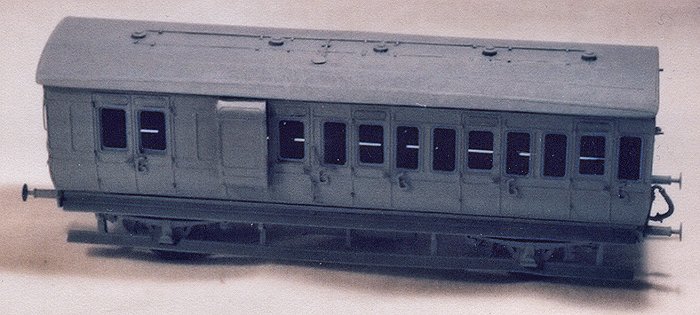
For many years now, the Ratio 4-wheelers have been the mainstay coaching stock of many GW branch line layouts. So much so that the coaches became a cliché; the moulds wore out and the kits were taken off the market. Fortunately, the manufacturers have refurbished the moulds and relaunched the kits. Shirescenes produce etched sides that allow the production of alternative coaches and a milk van to reduce the cliché effect. This article examines the building of a T36 Brake Third using the Ratio kit and the Shirescenes sides. It should be noted that whilst this article concerns specifically the brake third body and 3-compartment etched sides, it is fully expected that the general principles apply to the other etched sides and plastic bodies in the respective ranges. It should also be noted that Shirescenes supply etched ends and Mainly Trains an etched underframe kit. Undoubtedly useful as they are, this article does not evaluate them – although I believe that was I starting again, I would use both!
Examining both the kits and the instructions, it is clear that some care will have to be taken, as both sets of instructions are rather brief. Furthermore, the Shirescenes instructions are especially short of prototype information and the Ratio instructions don't rate highly either! Painting details are also skimpy – to the point of virtual non-existence in the Shirescenes instructions. The Ratio kit that I used was a couple of years old and had been produced before the moulds had been refurbished. It suffered from a number of defects that I trust have been rectified in the relaunched kits. These included the presence of excessive flash and the fragility of the underframe parts – particularly the axleguard tie rods and the stepboards. The Shirescenes sides were crisply etched and appeared to contain no obvious defects. Dimensions weren't checked as the instructions state that the coach length has been adjusted to suit the Ratio underframe. Detailing parts Before starting assembly, consideration was given to the choice of wheels and couplings, to superdetailing and to the need to strengthen or replace the more fragile plastic parts such as buffers and the aforementioned axleguard tie bars. Given the long wheelbase, the need for compensation or springing was also considered. I chose not to compensate or spring – a choice available in OO and EM but not in P4. The coach can easily be built with three-point suspension and I have built other Ratio 4-wheelers that way in EM. Dependant upon the level of detailing, a number of additional items will have to be purchased. For the vehicle detailed as described, a suggested shopping list is:
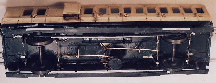
Adhesives Before starting construction, a word first about adhesives. The Shirescenes instructions suggest superglue, which I used for all metal-to-metal joints. With the exception of fitting the compartment partitions, which utilised the gap-filling properties of epoxy resin, all metal-to-plastic joints also used superglue. I chose to use the most viscous formulation and found it to be useful for its slight gap-filling properties, particularly when fitting the grab handles and other small detailing parts. Plastic-to-plastic joints were completed with Liquid Poly, applied with a small paintbrush. Assembling the Ratio parts Construction starts with the floor and the solebar/axleguard assemblies from the Ratio kit. Carefully open the holes in the back of the axle boxes and fit brass bearings. Ensuring that all flash is removed, glue the solebars to the floor. Before the glue sets, insert the wheels (I used Gibson EM 14mm Mansell wheels) into the bearings. Use elastic bands to ensure that the axleboxes fit snugly to the ends of the axles. Place the assembly on its wheels on a flat surface (such as a glass sheet) and with a weight on the floor; allow the glue to firmly set. Prepare the coach ends by removing flash and any moulded features that are to be replaced during the detailing process. Obvious candidates here are the buffer base plates, handrails, lamp irons and the handles of the gas valve control lever. Having removed these, it is necessary to widen the ends (I forgot to!) to allow for the reduced thickness of the brass sides in comparison with the plastic parts. Glue a length of 0.020x0.040in styrene to each side edge, flush with the end of the coach and let the glue dry. Glue a second length of 0.020" x 0.040" styrene to each side, about 0.005" proud of the previous strip, to represent the capping strip over the panel jointing. Once again, let the glue dry. Glue the plastic ends, now 2mm wider, to the floor / underframe assembly. Adding the Shirescenes sides The sides can be removed from the etch and the tumblehome formed as described in the Shirescenes instructions. The flanges should be formed at the top and bottom of the sides, but those at the ends should be left unfolded. A scoring process is described in the instruction that allows the flanges to be folded more tightly at the top and bottom of the coach sides. Don't miss this step as I did – it permits a tighter fold. Offer up the sides to the coach. At this point you will find, as I did, that the end flanges need to be removed from the etched sides. Cut these away carefully and file away the remains of the tabs. At this point, one can chose to complete the detailing of the sides before fitting them to the coach – I would recommended doing so if assembling by soldering. As I was using adhesives, I decided not to. Carefully aligning the profiled edges, spot-glue one side to the coach. Place the coach back on the glass plate, apply the weight again and allow the glue to set firmly. Offer up the second side to the coach. Taking extreme care and remembering that this is the last chance to remove any twist in the coach body, spot-glue the second side to the coach, place it back on the glass plate, apply the weight and allow the glue to set completely. Once set, finish-glue the previously spot-glued joints and put the coach aside (weighted and back on the glass plate!) whilst the glue sets.' Improving the underframe Given the fragility of the axleguard tie bars, one or both may have broken by this time. Fitting the stepboards now will protect the tie bars, but at the cost of possible damage to the stepboards. These are themselves fragile, particularly in the vulnerable area of the cutouts that clear the axle boxes. These cut-outs have to be opened up but as the stepboards obscure the lower part of the axle boxes, judicious filing of the lower front face of the box (which won't be seen) will allow the minimum amount of material to be removed from the stepboards. Once assembled, the tie bars and stepboards will benefit from strengthening. The tie bars can be reinforced with 0.020" x 0.020" styrene applied to their rear. The stepboards can be strengthened in the area of the axlebox cutouts with sections of 0.010" x 0.040" styrene strip with the front edge chamfered to reduce its visibility. The outer stepboard hangers are also vulnerable items that can be reinforced by glueing strips of 0.005in x 1mm phosphor bronze strip to their rear faces.
Detailing the sides and interior Turning to the sides, these can be completed as described in the Shirescenes instructions. There are three potential problems to bear in mind. The separate droplight frames are supplied half etched and are glued into position with the half etched side towards the outside of the coach. Having done so, it will be necessary to re-drill the holes for the door handles – or glue the droplight frames in with the half etch towards the inside of the coach! The second problem that needs to be overcome concerns the mounting holes for the large curved grab handles by the Guard's doors. A hole appears to be missing on one side and in the wrong place on the other. Regarding the grab handles, I chose to replace the Guard's handles with 0.33mm brass wire. Finally, the passenger door grab handles are rather heavy looking. I decided to use them, as the coach is to be finished in workmen's garb – battered, bashed, painted all brown and filthy. If it is to be finished in chocolate and cream, it may be better to replace them with finer alternatives from Comet or Roxey. Compartment partitions can now be cut from 0.020" styrene sheet. These should be fitted between each passenger compartment and between the last passenger compartment and the Guard's compartment. I was not sure whether there was a partition between the Guard's compartment and the luggage space but erred on the side of practicality and fitted one to maintain the rigidity of the model. Detailing the ends
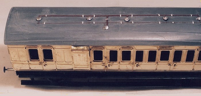
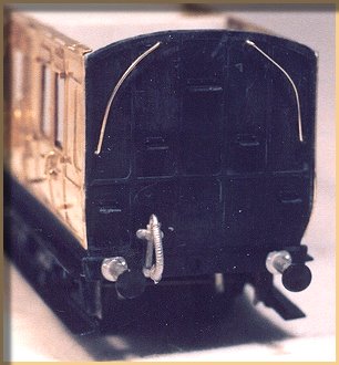
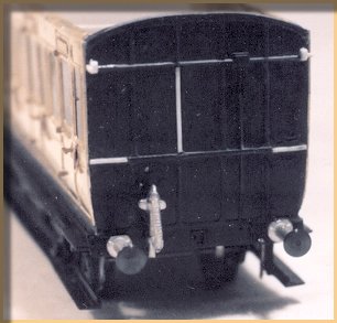
The ends can now be worked upon. Check the fit of the sides, which should be flush with the widened ends, which were previously made proud to represent the capping strips over the joints in the panelling. Locate the end with the steps, drill 0.4mm holes in the appropriate places and using 0.33mm brass wire, bend and fit the handrails. Drill both ends in the appropriate places and fold up etched lamp irons (not supplied in the kits!) and glue them into position. Turning now to the gas piping and control valves, the valve was usually located on one end of the coach (as in the Ratio kit). Gas piping ran up the end of the coach and on to the roof. Where the vehicle included a Guard's compartment, the control valve was often (but not always) within the compartment. From the internal valve, the piping ran up the wall of the compartment and led on to the roof underneath a circular cover plate. As the piping and control valve appeared to be poorly represented in the kit, I chose to assume that the coach followed the arrangement for Guard's vehicles. The piping and valve details were removed from the coach end and the mouldings made good where necessary using 0.010" x 0.020" styrene strip. Two small slivers of this strip were also used to represent the butterfly levers of the passenger's emergency brake valves, glueing them to the moulded housings high on one end of the coach. At solebar level, fit replacement buffers and vacuum pipes, having discarded the plastic parts supplied in the Ratio kit. Before laying aside the now completed body, add ballast (about 2 oz in total) to the coach over the wheels using either lead sheet or 'Liquid Lead'. The roof The roof can now be modified. Firstly, inside the roof, remove the ridges that locate the roof on the sides as they foul on the top flanges of the sides and prevent the roof fitting snugly. Turning now to the outside of the roof, pare away the mouldings of the gas lamp tops. Five replacement tops need to be fitted – four in the centre of the passenger and Guard's compartments and one on the centre line of the doors in the luggage compartment [see photo at top of page]. A sixth gas lamp top needs to be filed flat to represent the cover plate under which the gas pipes are led on to the roof. This plate needs to be offset from the coach centre line and aligned with the partition between the Guard's compartment and the last passenger compartment. Gas pipes can now be fitted using 0.020" and if representing the later, modified lighting, 0.010" styrene rod. Short lengths of 0.010" x 0.020" styrene strip should be added to represent the pipe securing straps. Conclusion The coach is now complete but for painting, glazing and the fitting of couplings. All in all, about four nights and two weekend's work to reach this point. It must be said however, that more than three quarters of that time has been taken up in writing this article and in taking the accompanying photographs. How do I rate the combination of the two kits? I found them to be well within my capabilities and that they have produced, with some judicious superdetailing, a good model that looks the part. Given support, possibly in the form of the local Model Railway Club, even a complete novice should be able to produce a good-looking coach from these two kits. Minus points – the instructions, particularly the lack of prototype details.
With the assistance of the GWR e-list and of John Lewis and Russ Elliott in particular, the following prototype data has become available: Ten coaches in total, built to Diagram T36 on Lot 978. Running numbers were 942 and 949 to 957.
© S.C. Farrow April 2005, used with permission |
||||||||||||||||||||||||||||||||||||||||||||||||||||||||||||||||||||||||||||||||||||||||||||||||||||||||||||||||||||
| Section Page | Previous Page | Next Page |