| Section Page | Previous Page | Next Page |
Fitting Sprat & Winkle couplingsby Mikkel Kjartan
Although the latest RTR offerings have helped enhance the looks of the RTR tension-lock coupling considerably, I still find them a bit too bulky and not quite reliable. A possible alternative is to use one of the more advanced do-it-yourself couplings, but (in 4mm at least) these require a degree of accuracy and patience a bit beyond me. Then there's the option of prototypical coupling with a home-crafted shunters-pole, but this is just too fiddly for my linking, and I can't quite get used to the proverbial big hand from the sky. Looking for something in-between, I have therefore taken to the fairly well-known Sprat & Winkle coupling, which – although certainly a compromise in some respects – has proven quite reliable and fairly easy to fit. These are available in 2, 3, 4 and 7mm scale versions. I do find the delayed-action feature of these couplings simple and effective (usual disclaimer), and a big plus for me is that they allow features such as cosmetic 3-links to be retained. The following is a brief run-down of my own experiences with fitting the Sprat & Winkle to 4mm stock. Note that you can see a detailed description of the actual procedure of fitting the couplings on the MSE website, which apart from being a sales outlet has downloadable instructions. The MSE site also has details on various extra parts not described here (including custom-made mounting plates). One-hook operation
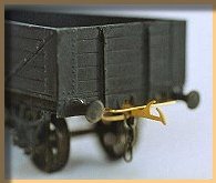
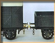
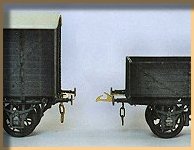
As I Model in 4mm my choice was between either the standard 4mm version or the 'finescale' version. The latter is in fact intended for 3mm modellers but works fine for 4mm (including OO), as long as your curves are not too severe (i.e. less than 4' radius according to MSE). This is fortunate because the standard version is rather too large for my liking. In fact, even the finescale version is a bit more prominent than I would personally have wished for, especially when uncoupled. To minimize the visual impact I therefore fit a coupling hook to one end only, adding just the loop at the other end. This approach obviously requires stock to be facing in a particular direction when placed on the track, but on my layouts (and I think most others) this isn't really a problem. The absence of a coupling at one end also facilitates the fitting process (since you only have to fit one hook per wagon) and means I can add a prototypical (but cosmetic) coupling hook here instead, enhancing appearances a bit. Mounting the couplings
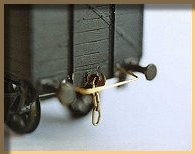
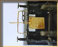
The coupling hook features a square 'paddle' at one end, which works as a counterweight beneath the wagon or coach body. The instructions suggest two possible ways of mounting the hook: An 'Upper' method in which the coupling hook is inserted through the headstocks (i.e. the 'buffer beam' of the wagon), and a 'Lower' method in which the hook rests immediately below the headstocks, hinged to the wagon floor with wire bent to the shape of a paper staple. It is necessary to standardize on one of these two methods, and in principle I prefer the latter, which also comes recommended in the instructions: This requires only minor modification to the wagon or coach body, and is also in my opinion rather less fiddly. That said, I have made two minor modifications to this approach: Firstly, I always replace the curled-up wire included in the pack with straight brass wire from Alan Gibson. This makes it far easier to craft the wire-staple needed for fitting the paddle. The staple is then fitted to a section of square plastic rod mounted on the wagon floor. The plastic rod is not always necessary on RTR wagons – it depends on the distance between the floor and the lower edge of the headstocks. Secondly, I find that the 'Lower' method of mounting the coupling can sometimes give problems in ensuring that the coupling hook is fully horisontal: Exactly because it is underhung, the hook may come to rest at a slight upward angle against the bar of the loop on some wagons, which is neither aesthetically pleasing nor good for operation. I don't think it's just me, as I have heard others mention the problem also. My solution is rather crude I suppose, but effective: I simply open out a slight slot in the wagon just above the coupling hook, thereby allowing it to move freely to a full horisontal position against the loop. This may not be to everyones taste, but the slot is really quite unnoticeable and can always be padded over with a filler if the coupling is removed. Magnetic uncoupling
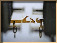
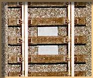
Uncoupling is by means of magnets located beneath the track, nested into the track base. The magnets attract the 3-links, thus tilting the hook downwards. When moving back up, the hook comes to rest in a position which allows the wagon to be propelled forward and left whereever you want it in the siding. Hence the 'delayed-action' concept. For me this works well, with one important modification: because I use only one coupling hook, the very powerful magnets occasionally uncouple the stock even when they are not supposed to, i.e. when the stock is passing slowly by. This happens even with a good layer of ballast above the magnets, and attempts with a sliver of Plastikard above the magnet doesn't help much either. Again, I resort to cave-man technology for the solution: I simply break the magnets in half, thereby reducing the overall magnetic field. I say 'break' because cutting will get you nowehere with these magnets – they need to be broken in two by holding the magnet with one pair of pliers and breaking downwards with another pair. Crude stuff, but it works. |
| Section Page | Previous Page | Next Page |