A semi-permanent coach coupling
by Steve Farrow
On many layouts, coaches are run together in rakes and are not separated during an operating session. It makes sense therefore to join them together with semi-permanent couplings, which tend to be less obtrusive than all but the smallest of the currently available automatic couplings. The coaches will not be parted by whatever uncoupling mechanism is used for uncoupling vehicles during shunting. My coaches are fitted with Sprat & Wrinkle couplings at the outer ends of the rakes and with these couplings within the rakes.
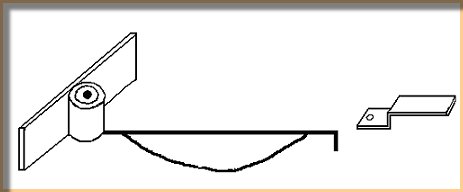
The couplings are easily made and fit behind the buffer beam. They are more unobtrusive than pretty well any automatic coupling and can easily be disguised as a screw coupling and vacuum / steam pipe. They are easy to couple and uncouple, even when the coaches are fitted with working corridor connectors. If manufactured and fitted as described, they will not interfere with the coach bogies.
Materials
- A length of 2mm wide by 0.25mm thick brass or nickel silver strip
- A length of copper or brass tube with a bore of 0.8mm
- A length of 0.7mm brass or nickel silver wire
- A length of 0.45mm brass or nickel silver wire
The hook mounting
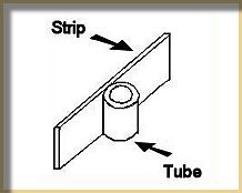
- Before cutting to size – solder the tube across the strip, about 4mm from the end.
- Cut and file the tube and strip to size. Aim for the strip to be about 10mm long and the tube to be the same width as the strip.
The hook plate
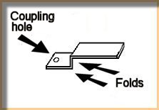
- Before cutting to size, drill a 0.85mm hole centrally in one end of a piece of strip.
- Offer up the strip to the vehicle to which it is to be fitted. Bend the strip as shown in the diagram, aiming for the coupling hole to protrude 1 to 2mm out from the buffer beam. Ensure that this measurement is the same on each vehicle fitted with the coupling. Position the second fold so that you will later be able to glue the hook plate to the underside of the floor of the vehicle, behind the buffer beam.
- Round off the corners of the protruding part of the hook plate.
- Cut to length (about 10mm) the portion of the plate that will be glued to the floor of the vehicle.
The hook
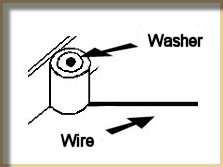
- Drill a 0.8mm hole centrally in one end of (another) piece of strip. Solder to one end of a length of 0.7mm wire.
- Trim and file the strip to become a small flat washer that will retain the wire in the tube.
- Fit the wire through the tube and bend it through 90 degrees. Leave the wire overlength until the coupling is fitted to the vehicle.
Fitting the couplings
- Glue the hook plate to one end of the coach. The folds allow the plate to be attached both to the rear of the buffer beam and to the floor of the vehicle.
- Glue the hook-mounting bar behind the buffer beam at the other end of the coach. Take care not to get glue on the washer retaining the hook in the tube of the mounting bar. This washer will inevitably be close to the floor of the vehicle. Once fitted, the hook should pivot in the tube of the mounting bar.
- The hook now needs to be formed by bending down and trimming to length. An exact dimension cannot be specified as there are a number of factors to be taken into account:
– Radius of curves on the layout
– Length of the vehicle
– Whether the vehicle is 4- or 6-wheeled or fitted with bogies
– Whether the buffers are fixed or sprung
As a guide, bending the hook so that buffers are about 5-6mm apart on a straight, appears to be correct for 4- and 6-wheel coaches with fixed buffers on a layout with 3' radius curves.
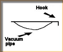
Finally, using a short bit of 0.45mm wire, simulate the vacuum pipe. Although not shown in the sketch, further short bits of wire can be used to simulate the couplings of the vacuum pipe and the various parts of the screw coupling. It is probably best to attach all of these parts with glue.
|