Detailing options for the RTR Siphons
by John Lewis
On this page, John provides a few tips for detailing the Hornby (ex-Airfix/Dapol) Siphons G and H, and the (now discontinued) Lima Siphon G. The notes were first provided by John in reponse to a query on the GWR4mm list.
| The Hornby (ex-Airfix/Dapol) outside-framed Siphon G to dia O11 |
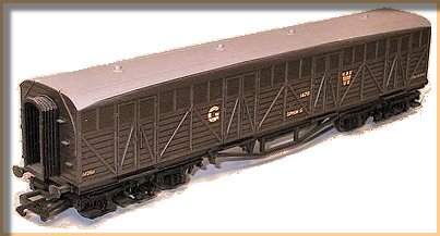 |
Much depends on how keen you are and the period you model! You ought in any case to consult the HMRS book "GWR Siphons" by Slinn and Clarke, or at least follow a decent photograph.
Body and roof
- As far as I am aware the bodies are pretty accurate, but if you are a dab hand with a scalpel you could replace the grab handles.
- The gangway connectors could/should be replaced by the correct pattern – either suspension hung or the scissors pattern, inside framed and outside framed respectively.
- The lamp brackets can be replaced with metal ones of the appropriate pattern.
- You could add gas pipes to the roof using very thin plastic "wire" unless you are modelling one with electric light in which case the gas lamps should be removed, see below.
- Post-WWII, some inside framed Siphons had ventilators on the roofs, see the HMRS book.
| The Hornby (ex-Airfix/Dapol) Siphon H to dia O12, here in BR livery |
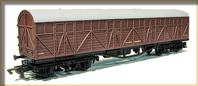 |
Underframe
The underframe is the biggest problem area. You might consider some/all of the following:
- Change the truss rods for brass angle, but note that the earliest ones (1462–74) had flat bar trussing with adjustable queenposts (like Toplight Bars I and II coaches) and the next batch (1442–1461) had multibar trussing.
- The buffers need replacing by the Churchward rectangular shank pattern. The outside framed version had ones with oval heads, the inside framed ones had large circular heads.
- The couplings can be replaced by screw ones.
- Vacuum pipes and (except for the summer) steam heating pipes should be added. Ideally you should model the steam heat pipe with its condensate trap anyway.
- The brake gear should be upgraded with Churchward type vacuum cylinders and Churchward type hand brakes, although the later ones of the inside framed varieties had lever handbrakes.
- The gas cylinders of outside framed Siphons G (Diag O11) can be changed for cast ones, unless you are modeling one from Lot 1347 (1290–1309) which were electrically lit, as were the vertically planked inside framed ones (O33 etc), in these cases you should fit a dynamo and battery boxes etc.
- You should fit appropriate bogies. I think I am right in saying that the models are fitted with BR Mk1 ones. These are quite close to the GWR 8' 6" ones fitted to O33 vans 2772/8–80/87/8/92/95–2800 of Lot 1631 built in 1940, otherwise they should be changed.
| The Lima inside-framed Siphon G dia O33 |
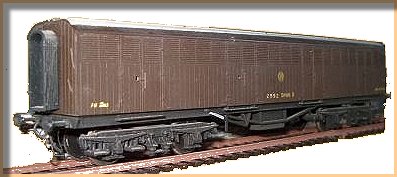 |
Finish
Then paint, if necessary, add the correct livery if you do not like what is on the model, and an appropriate number. You might consider weathering quite heavily – at least in BR days they seem not to have been cleaned externally. If your modelling period is the 1920s you might consider starting with the BR model, as ones built before mid-1922 were painted lake.
In theory it is possible to produce the O10 vehicle 1502 which had end doors from an O11, but you would have to rebuild the ends.
John Lewis
Editors note:
There was a detailing kit for the Hornby Siphons available from Jackson Evans. This may or may not have been the ex- Hayes Developments kit, which included bogies, gas tanks, vacuum cylinders, buffers and etched parts for replacement brake gear and rodding.
Blacksmith Models once did a 4mm GWR Siphon Underframe & Bogie Kit, which probably stems from their own etched brass versions of Siphons G and H. The same manufacturer also produced an etched kit to convert the Lima Siphon G to a BR Diagram 062.
|