|
GWR Goods Brake Vans
by Russ Elliott
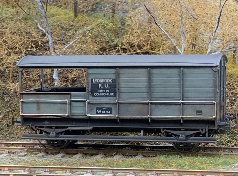
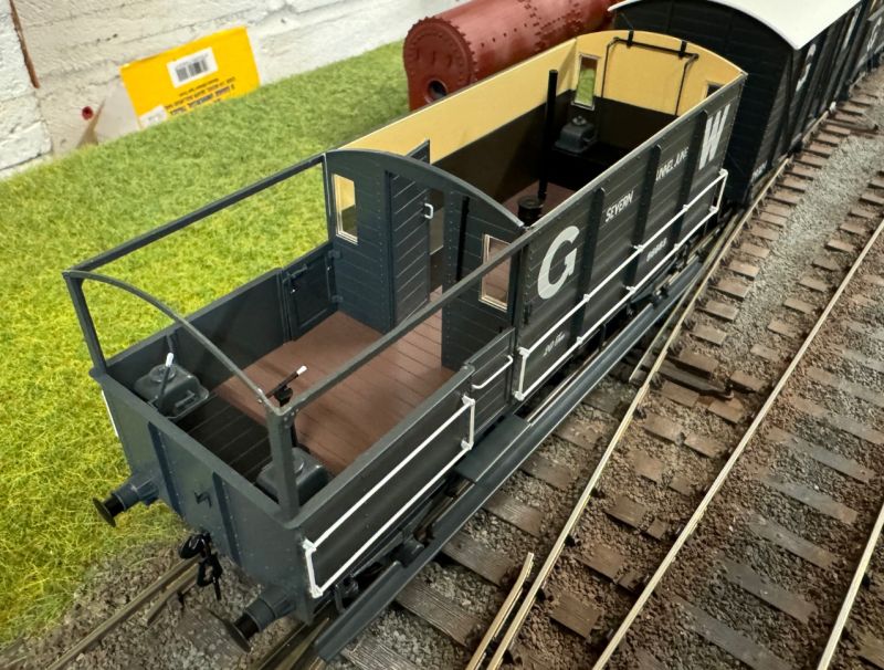
A nicely weathered Rapido diagram AA20, with custom Railtec transfers, by Alex Warren, seen here on his Lydbrook Dean layout.
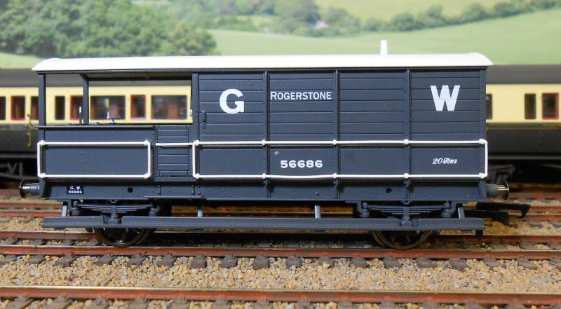
Hornby's excellent AA15 brake van, pictured by Robin Sweet on his layout. With its angled footboard hangers, J-hanger springs and GWR axleboxes, Hornby's model depicts the penultimate lot (lot 910, running numbers 68601 – 700), and possibly lot 888 (for running numbers, see table below), although unfortunately Hornby has chosen a running number from an earlier lot (853), which had swing-link spring hangers and round-section footboard stanchions.
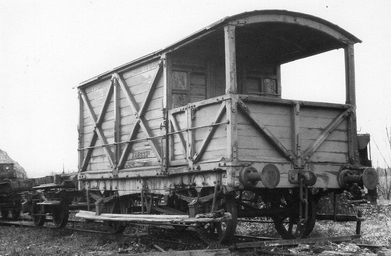
An outside-framed wooden-underframe van of the 1874–81 design. Most of these timber-solebar vans never survived long enough on the GWR to be given an official diagram number, but the body style would be adopted in what was later classed as the AA16 design. This survivor was sold on from the GWR for use on one of Colonel Stephen's railways, and is pictured on the Kent and East Sussex Railway, but its current whereabouts and condition is not known. On subsequent lots of these outside-framed vans from 1882, timber solebars were replaced by 'bulb-iron' section, and from 1886 (beginning with lot 355) the solebar became 9" x 3" channel section.
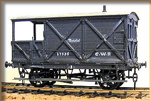
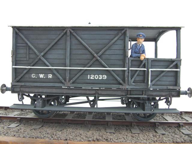
Diagram AA16 in 4mm, with its original lever brakes and pre-1904 lettering, built by Dave Perkins from a D&S kit |
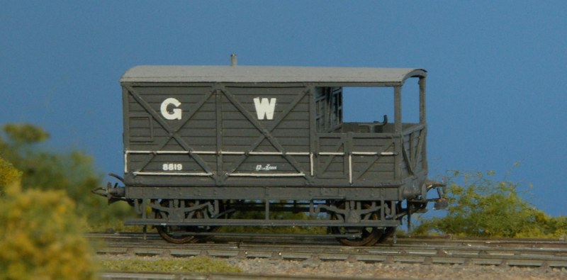
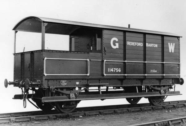
7mm 6-wheel Brake Van diagram AA1, built from a PECO (ex-Webster) kit by Roger Bailey. The extra axle on these heavier vans increased the braking power. |
A remarkably neat 2mm scale AA16 built by John Brenchley from a David Eveleigh kit. These vans began to disappear from traffic department use in the 1920s, but some survived, many converted to tool vans under Signal & Telegraph Department use, until the late 1940s.
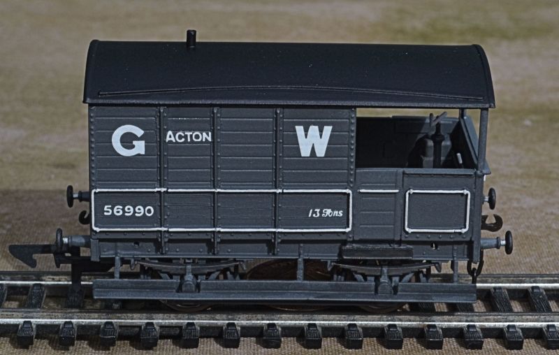
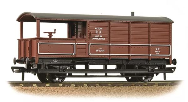
An AA7 'Acton' van produced from a venerable Ratio kit by Tony Richards. Note the unevenness of the stanchion spacing on the cabin. Further details of the build can be found on at the Swansea Railway Modellers Group.
Variations and details
Side and end plating, for post-1889 vans
Early vans were of fully-planked construction, with a diagonal bracing strip (often replaced later by angle section) on the verandah sides. On diagram AA13 (of 1913), the verandah sides and ends were constructed from steel sheeting. From diagram AA14 onward, the lower sections of the sides and the outer end of the cabin were plated with steel sheeting. There was only one AA14 built (a Permanent Way Brake Van), so the first non-departmental diagram to feature steel verandahs and cabin plating was the AA15 of 1918. The plating was either ⅜" or ¼" thick.
Most older vans were retrofitted with cabin plating and/or had their verandah sides and ends replaced. Planked verandahs and unplated cabin sections could still be seen into the 1920s.
Handrail styles and their mounting
Handrail construction prior to 1912 was of individual forged pieces of solid bar, thought to be ¾" diameter, bent down and flattened at each end, and attached to the bodywork with bolts. Where the handrails formed a corner, the body bolt was shared. At the ends of vans, it was common for the vertical handrails to extend below the bodywork. Horizontal handrails were usually not fixed to intermediate vertical bodywork T-stanchions, although they were fixed with handrail knobs on the wooden-framed AA16s. This style of handrail was last fitted for new construction on the AA11s.
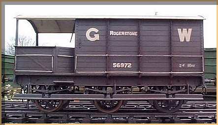
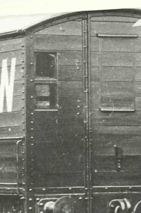
Originally, the lower handrail was only present on the verandah sides and the last section of the cabin, as shown in the adjacent AA1 detail (c 1904), and in the AA3 17539 picture below.
(Note the guard's name painted on the sides of these early vehicles.) |
 |
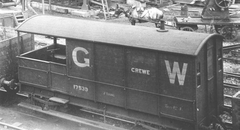
AA3 17539 in its early years has no roof rainstrips, and its verandah shows the early style of hinged seats in each corner giving access to the front sandboxes.
| AA3 56378 with its sides plated and lower footboards upgraded, probably mid to late 1920s |
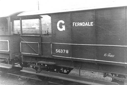 |
From c 1902 onward, the lower handrail was extended for the full width of the cabin. With the exception of the Permanent Way vans, older vehicles were upgraded between 1904 and 1911 to the post-1902 style.
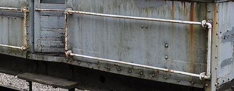
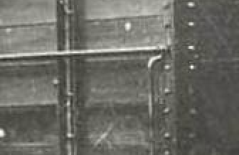
| After 1912, handrails were 1 3⁄32" o/d (nominal) gas pipe, joined with gas pipe fittings at the corners. The handrails were also secured to the intermediate T-section side stanchions. Most older vans were retrofitted with this style, but all AA16s, some AA1s and many AA3s kept the pre-1912 styles throughout their lives. |
 |
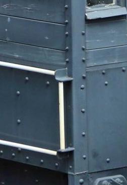
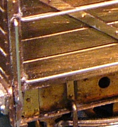
| From AA23, angle brackets held the handrails instead of pipe joints. |
 |
Handrails were originally painted bodywork grey, but a change to white was made during WWI.
Wheelbases and body lengths
| Diagram |
Wheelbase |
Body length |
| AA1 (6-wheel) |
6'6" + 6'6" |
20'0" |
| AA7 |
9'0" |
16'0" |
| AA8, AA16, AA24 |
11'6" * |
18'0" |
| AA2, AA3, AA4, AA5, AA6, AA9, AA10, AA12, AA14 |
13'0" |
20'0" |
| AA11, AA13, AA15, AA17, AA18, AA19, AA20, AA21, AA22, AA23 |
16'0" |
24'0" |
| * there were some wheelbase variations in the AA16 vehicles, some being 11'8" and 10'0" |
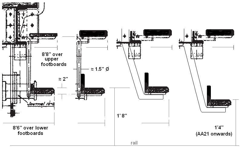
Footboard styles and their supports
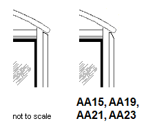
Footboards were standardised in their over-width dimensions and their heights above rail level. The following sketch, based on the original drawing for an AA3, shows the development of styles – from left to right:
- Lower footboards were suspended from vertical round section forged stanchions mounted tight to the front of the solebar, and the upper step was initially a thinner section.
- The rear vertical piece of the lower footboard was made higher from diagram AA13 onward, and the upper footboards were thickened up to the standard (approx 2") thickness. Some vans retained their original lower footboard style, but most older vans were retrofitted with the newer-style lower footboards.
- From diagram AA15 onward, angled T-section hangers were introduced for the inner two hangers of the lower footboards. Some AA15s had all four lower footboard hangers of the new pattern. Most subsequent diagrams retained a mixture of the two types.
- The lower footboard height above rail level was lowered from diagram AA21 onward. Some AA20 vans had their lower footboards at the lower level, and it seems probable the later batches of AA20 vans had the new height setting.
Lettering and branding location
For post-1904 25" lettering, the bottom of the G and the W was in line with the bottom of the 5th plank down. For post-1920 16" lettering, the bottom of the G and the W was in line with the bottom of the 4th plank down.
Where the name was short enough, the depot branding was usually placed in the penultimate panel at the verandah end, on the 3rd plank down. If the name was long, like 'Severn Tunnel Junc', it was spread over the two middle panels. Some early vans had the depot branding on a cast plate.
Numbers and all letters of the depot allocation, apart from the initial letter, were 5" high. The size of the initial letter of the depot allocation was not specified, but is approximately 6" high.
The positioning of the running number varied according to era.
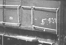
Between 1922 and 1936, those AA3s weighted to 25T had a white star (in the fifth plank down) below the depot allocation. Between 1934 and 1943, AA20s 68753 – 90/2 – 6, and all AA21s, carried a white 'S' below the depot allocation to indicate they had been weighted to 25T and/or had been fitted with vacuum brakes.
The 'R.U.' (Restricted User) marking was introduced probably in September 1943 to indicate vans set aside at certain depots for specific local workings. At a subsequent date, probably c 1952, former GWR Brake Vans were branded 'Not In Common Use', which indicated the vans were supposed to remain on WR workings and not be allowed to wander off elsewhere. The meaning of 'R.U.' was widened in October 1960 to include inter-District or local workings. GWR goods brake vans were barred from traffic use as brakevans in late 1965.
Vacuum-fitted vehicles were repainted bauxite in BR(W) times.
Verandah and interior layout
On the verandah of early vehicles, front sandboxes were contained under separate hinged seats, but there seemed to be a change during the early AA3 construction to a single cross-seat across the end of the verandah, with enlarged sandbox pots sitting on the cross-seat. This cross-seat style was adopted in subsequent diagrams, except AA21, where the vacuum cylinder occupied the space between the front sandboxes. On the AA15, additional seats were provided on each side of the verandah inboard from the verandah doors, but these side seats did not appear in subsequent diagrams. The interiors of the verandah were in bodywork grey, with the underside of the roof painted white. The verandah floor was unpainted. On vacuum-fitted vehicles, the brakesetter was painted red in BR(W) times.
In the cabin, a cross-seat was provided at the end for the sandboxes in a similar style to the verandah. Additional hinged seats/lockers were provided, and, in late diagrams, a desk. The stove was offset approximately 16" from the vehicle centreline, with its flue angled to the chimney position. The interior was painted dark chocolate up to waist level, cream above the waistline, and white for the roof underside. The stove and fittings were black. In diagrams AA19 and AA20, the guard's seat was apparently padded, and "about 3' away from the desk". No interior lighting was provided.
Neal Prescott's interior painting of his 7mm Dapol AA15
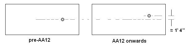
Chimney position
| Chimneys (4" in diameter) were on the centreline of early vehicles, but were offset from diagram AA12 onward. |
 |
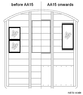
Cabin windows
Windows on the ends of cabins were initially of a two-pane style, but from 1918 (diagram AA15 onward) were a single-pane style, in a higher position, and quickly acquired rain strips and sills, as did the lamp hatches. Most older vans were retrofitted with the single-pane window style.
 |
Original style cabin windows and lamp hatch on diagram AA1, c 1904/5
(This van, 56933, was allocated to Swindon and was chosen as one of the vehicles to trial the application of the 25" size of 'G W'.) |
Running gear details
- Brakes On the AA16 vans, 4-shoe lever brakes were fitted, most were modified later (generally during WWI) to 8-shoe clasp-type. On all other diagrams, 8-shoe clasp-brakes were fitted as standard (12-shoe in the case of the 6-wheel AA1).
- Axleboxes Grease boxes were initially fitted on the AA16, AA3, AA6 and AA8, but began to be replaced by oil boxes c 1900. On the lighter vans, 8" x 4" and later 8" x 4½" oil boxes were normal, and on the heavier vans, 10" x 5" boxes were used. RCH 10" x 5" fittings prevailed from the last AA15 lot and subsequently.
- Springs Springs were 4'6", suspended from J-hangers or swing-links. The 6-wheel diagram AA1 had swing-links on the outer axles, but J-hangers on the centre axle. Springs on the heavier vans were a bit larger than those on the lighter vans.
- Buffers 1'6" buffers were standard, of various types, with the self-contained type making an appearance on diagram AA15 and last appearing on the AA18. The self-contained type began to be fitted to AA16 vans during WWI. RCH style prevailed from AA19 onward. AA20 had either RCH or GWR buffers, and AA21 had RCH buffers. Those vehicles having screw couplings had 1'8½" buffers.
- Couplings 3-link couplings were fitted initially to the older vans, but instanter couplings became standard from c 1918 for the unfitted vehicles, and were usually fitted subsequently to older vehicles. Screw couplings were fitted to all vehicles that were fully-fitted.
- Vacuum-fitting Some of the members of the following diagrams were fitted with through pipes (and thus becoming telegraphic code 'Toad A'): AA2, AA5, AA6, AA11, AA15, AA20. All of AA7, AA9 and AA10 were so fitted. These vehicles did not have a vacuum cylinder, although AA5s were fitted with a cylinder in the 1900s. AA21 was fitted with full vacuum brake gear, with a cylinder, and had screw couplings. A few of the AA23 vans became fully-fitted in BR days.
- Wheels 8-spoke were the norm in early GWR days, with 3-hole disc wheels making an appearance on AA19 in 1927, and becoming the norm for subsequent new build.
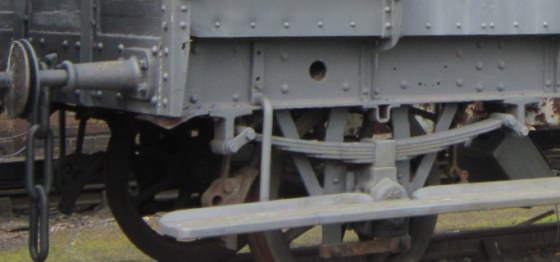
AA3 56400 with GWR buffers, light springs, swing-link spring hangers, round-section footboard hangers, and shallow rear upstand on lower footboard
Thanks to Gareth Price for these detail pics. Click on the image to go to the original picture, from which other GWR brake van pictures can be reached.
|
 |
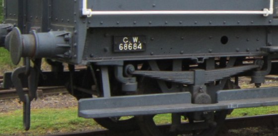
| AA15 68684, with GWR self-contained buffers, GWR 10" x 5" axleboxes, J-hanger spring hangers, and angled footboard hangers. |
|
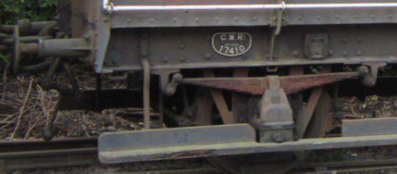
| AA21 17410 with 1'8½" RCH buffers, RCH boxes and footboard in the lower position |
 |
Other detail variations
- Side stanchions (at solebar area) On diagrams up to AA23, stanchions on the sides of the cabin 'tucked under' at the solebar in traditional GWR fashion, but on AA23 they went straight down below the bodywork, attaching to the bottom of the solebar.
 Side stanchions (at roof level) On diagrams AA15, AA19, AA21 and AA23, the chamfer at the top of the side stanchions was visible. On other diagrams, there was no visible chamfer at the top of the stanchions. Side stanchions (at roof level) On diagrams AA15, AA19, AA21 and AA23, the chamfer at the top of the side stanchions was visible. On other diagrams, there was no visible chamfer at the top of the stanchions.
- Cabin side bracing Diagram AA11 had diagonal L-section bracing on the end panels of the cabin sides. Some AA11s were later modified with large A-bracing across across all four side panels. Diagonal bracing was fitted to the middle two side panels on some AA19, AA20 and AA21 vehicles later in their lives.
- Lamp brackets On the outside-framed vans, there were six lamp brackets - two were central on the lower part of the ends, the other four on each corner of the cabin, two of which were accessible via lamp hatches in the sides. After 1889, only four lamp brackets were carried, with only two side lamp brackets, located on the sides at the verandah-end corner of the cabin.
- Roof rainstrips Although possibly not fitted initially on the early diagrams, many later brake van diagrams had shallow rainstrips on the roof in GWR times, and most vans had acquired them by the BR(W) era. Rainstrips of a 'double shallow vee' shape could be seen on some vans in the 1910–20 era, particularly on AA16s.
- Lamp hatches On early diagrams, the lamp hatch at the end of the cabin was flush with the bodywork, but on later diagrams it was slightly recessed. There were slight variations in the height setting of the lamp hatch.
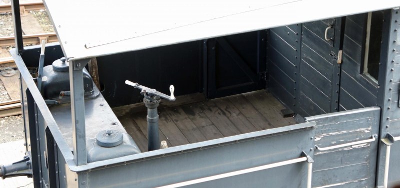
Verandah of an AA23 brake van at Didcot, showing the sandboxes, sanding levers and brake standard. Brake standards were offset from the vehicle centreline, the offset distance varying between diagrams. Verandah floors were unpainted. Photo courtesy of Godfrey Glyn.
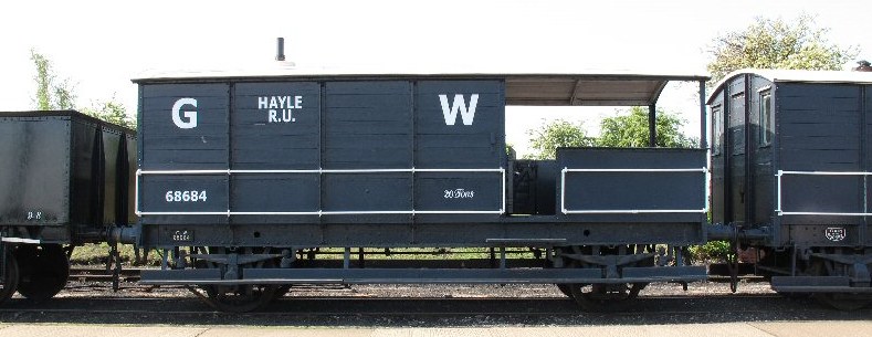
Preserved AA15 68684 at GWS Didcot, image courtesy Nick Ryan
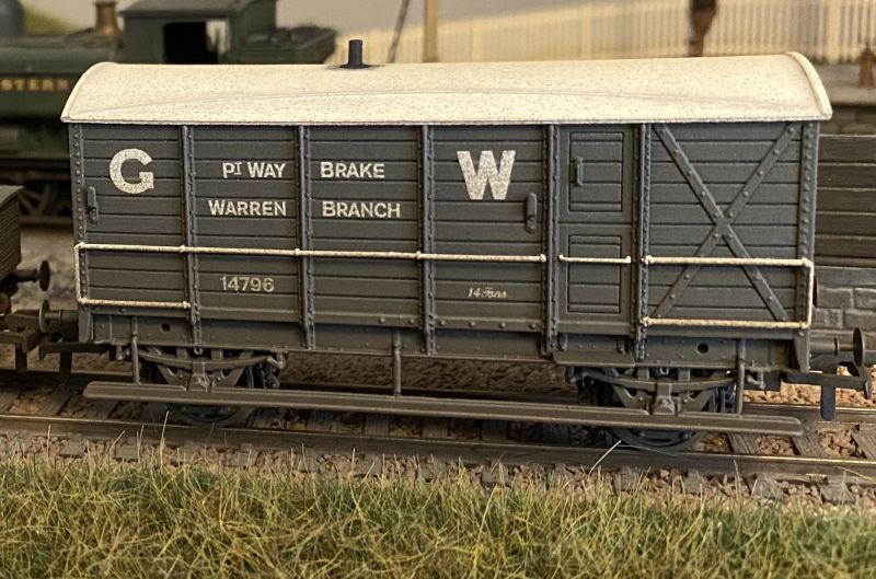
Chris Nicholls' excellent AA6 Permanent Way Brake, the body being a 3D print from Chris' CAD, and the chassis is from an Oxford Rail brake van. Seen here running on Chris' Warren Branch layout.
| An early (1934 build) AA20 brake van, with footboards set at the pre-AA21 standard height |
 |
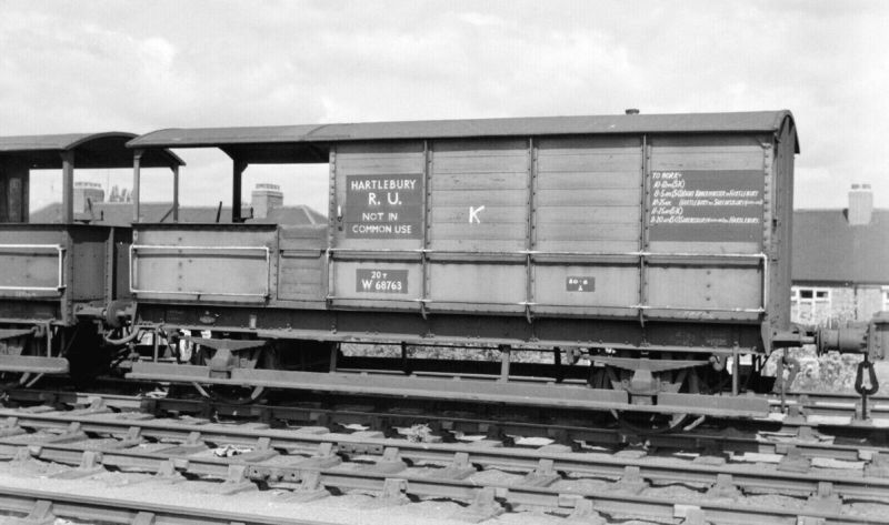
AA20 diagram W68763 in BR days showing the typical lettering style (white on black background panels) on the BR(W) light grey body colour. The lower footboard is in the lower post-AA21 standard height. (Pictured at Hanwell Bridge Sidings, 9 May 1965.)
'Road Vans'
A 'Road Van' was a brake van fitted with Mink-style wooden doors in each side which converted the cabin or part of it into a goods/parcels compartment. Only five Road Vans were thought to be built: 8804, 8864 and 12022 (from AA16) and 17600 and 56448 (from AA3). The AA3 vans were fitted with screw couplings, vacuum brake, and steam pipes, and could therefore work as part of a passenger train.
XP-rated 56448 is seen allocated to Cirencester c 1958. |
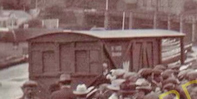
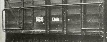
A fuzzy picture extract of 8804 at a very busy St Ives. It is lettered 'St Ives Branch'. It is not clear why the branch felt the need for a Road Van – the frequent passenger service had ample parcels and luggage provision. A Road Van was also used on the Helston branch. |
Tool vans
Between 1925 and 1934, 13 AA16s were transferred to the Signal Department as tool vans. They were numbered 90774/5/91/6/813/42/74/913/29/30/64.
Diagrams, build dates, lot numbers and running numbers
Below is a table of GWR Goods Brake Van diagrams for 1874 onward. The listings are GWR designs only, and do not include absorbed types. For illustrations and details, refer to 'GWR Goods Wagons' by Atkins, Beard & Tourret. Thanks to Steve Daly for providing the initial information for this listing.
Sample allocations of GWR Brake Vans, with an emphasis on the post-grouping era, is given in this Microsoft Word file.
| Dia |
Build period |
Tare weight
(T – c) |
Lot numbers, running numbers, quantities and totals
(os = old series of lot numbers) |
| – |
1874 – 1881 |
≈ 10 – 0 |
osL126 17770 – 94 (25); osL151 17807 – 26 (20); osL154 including 8759/65; 8835, 17827 – 41 (30); osL157 14678/9 (2, Engineers Dept); osL159 17842/3 (2); osL160 3236, 17844 – 61, 27743 (20); osL168 17865 – 82 (18); osL215 including 3228/32/8/44/50/3/5/6/60/6/71, 3924, 8327, 8826 – 8/33, 8875, 10115/32, 17885, 17934, 27733/4/6/42/88/9, 29737 (100)
(total 217) (these were 'AA16' outside-framed bodies on wooden underframes, but never survived long enough on the GWR to be given an official diagram number – the first 3 lots were initially built without a roof over the verandah section) |
| AA1 |
1900 – 1902 |
24 – 0 |
L336 56975 – 84 (10); L351 56965 – 74 (10); L358 56945 – 64 (20); L383 56923 – 44 (22)
(total 62) (6-wheel) |
| AA2 |
1902 – 1910 |
24 – 0
(later
25 – 0) |
L387 56905 – 22 (18); L388 17602 – 5/7 – 12/4 – 7/21/4/7 – 30 (20); L417 56885 – 904 (20); L464 17524/83/92, 17606/13/25/6/31 – 5/7/9 – 45/7/9/50/2/5 (25); L477 56855 – 84 (30); L523 56835 – 54 (20); L540 17619 etc (50); L549 17706 – 17/9 – 36/8 – 50/2 – 8 (50); L592 56810 – 34 (25); L642 17759 – 62/4 – 72/4 – 8/80/1 (20)
(total 278) |
| AA3 |
1889 – 1901 |
16 – 0
&
20 – 0
&
25 – 0
|
osL388 17862 (1); osL432 (part) 35827 – 9/31 – 65/7 – 76 (48); osL492 17505/18/20/35/9/40/54/6/8/69/96, 17822, 10085, 10100 etc (30); osL534 3251, 10131, 12023/4, 12775, 17512/5/7/55/7/71/81, 17651, 22783/90, 35792 – 826 (50); osL537 35692 – 791 (100); osL584 35672 – 91 (20); osL627 35622 – 71 (50); osL662 35602 – 21 (20); osL680 56001 – 20 (20); L5 56021 – 40 (20); L7 56041 – 60 (20); L11 56061 – 80 (20); L38 56081 – 100 (20); L57 56101 – 50 (50); L74 56151 – 70 (20); L94 56171 – 90 (20); L96 56191 – 210 (20); L136 56211 – 30 (20); L158 56231 – 60 (30); (10 special wheels); L174 56291 – 310 (50); L195 56311 – 30 (20); L221 56331 – 70 (40); L249 17503/7 – 10/3/23/6/9/31/2/4/7/8/46/9 – 51/61 plus one (20); L268 56371 – 95 (25); L282 56396 – 430 (35); L298 17506/64/5/7/8/70/2/3/7 – 81/4/6 – 91 (20); L327 17600 (1) (for Pontycyllio Branch, with side doors, screw couplings and vac brake); L338 56431 – 80 (50)
(total 840) |
| AA4 |
1892 |
14 – 0 |
osL432 (part) 35830/66 (2); osL648 35953 (1)
(total 3 plus ?) (Severn Tunnel) |
| AA5 |
1893 – 1901 |
14 – 0 |
L21 40370 (1); L24 40371 (1); L26 40372/3 (2); L31 40374/5 (2); L46 40376 (1); L50 40377 (1); L60 40378 (1); L64 40379 – 81 (3); L188 40384/5 (2); L213 40912 – 7 (6); L344 60760/1 (2); L361 60759 (to replace 14494) (1)
(total 23) (Ballast Plough and Brake Van) |
| AA6 |
1890 – 1900 |
14 – 0 |
osL531 14101, 14794, 40346 – 53 (10); osL564 BG 7826 Rb 40356 (1); osL575 BG 6586 Rn 40354 (1); osL594 BG 6635 Rn 40355 (1); osL642 40356/7 (2) (40356 was BG rebuild); osL665 40358 – 63 (6); L4 40358 – 63 (6); L115 40382/3 (2); L150 40923 – 30 (8); L199 40921/2 (2); L214 40918 – 20 (3); L244 40910/1 (2); L262 40908/9 (2); L269 60765 – 70 (6); L305 60762 – 4 (3)
(total 54) (Permanent Way Brake Van) |
| AA7 |
1897 – 1898 |
13 – 0 |
L206 56985 – 96 (12)
(total 12) (for Metropolitan lines) |
| AA8 |
1888 – 1890 |
12 – 8 |
osL445 17590/1 (2); osL523 17594 (1); osL568 17595 (1)
(total 4) (for Pontnewynydd Branch) |
| AA9 |
1905 – 1908 |
24 – 0 |
L489 60756 – 8 (3); L556 60754/5 (2)
(total 5) (Permanent Way Brake Van) |
| AA10 |
1908 – 1909 |
25 – 0 |
L605 60753 (1)
(total 1) (Ballast Plough and Brake Van) |
| AA11 |
1912 – 1913 |
13 – 0
&
16 – 0 |
L707 56483 (1); L724 56484 – 92 (9); L748 56493 – 502 (10); L749 56503 – 17 (15)
(total 35) |
| AA12 |
1914 – 1915 |
22 – 0 |
L799 (part) 17819 – 21/3 – 38 (19)
(total 19) (ex-PW Brake) |
| AA13 |
1913 – 1918 |
20 – 0
(24 – 0) |
L757 17901 – 50 (50); L773 17871 – 900 (30); L779 17839 – 54/6 – 61/3 – 70 (30); L799 (part) 17787 – 91/3 – 818 (31); L817 56518 – 82 (65); L840 56583 – 632 (50)
(total 256) |
| AA14 |
1914 – 1915 |
24 – 0 |
L795 (originally intended to be 60771 – 90, but only one built, given the number 14678; order closed 1928)
(total 1) (Permanent Way Brake Van) |
| AA15 |
1918 – 1927 |
20 – 0 |
L845 56633 – 82 (50); L853 56683 – 730 (48); L863 56733 – 82 (50); L888 17514/23/41, 17601/23/36/53/6/8/62/5, 17718/51/73/9/82 – 6, 17951 – 8/64/5 (30); L910 68601 – 700 (100); L932 68501 – 600 (100)
(total 378) |
| AA16 |
1882 – 1887 |
12 – 0 |
osL253 410, 3230/48/65/8/72, 8755/64/6/71/8/83/4/9/91, 8801/5/20/3 – 5/30/62/5/71/5, 10109/18/30, 17515, 17618, 17959 – 72, 22351, 31290 (50); osL260 35961 – 36000 (40); osL270 including 3231/7/52/7, 3921, 4110, 8798, 8806/11/31/4/67, 10096, 10103/14/20, 17973 – 18000, 22771, 31294, 35958 – 60 (50); osL300 including 3229/33/5/45/58/62/4/9/70, 4111, 8758/80/1/7/93/9, 8802/3/8/17/9, 10086/8/92/8, 10105/5/7/11/6/7/9/26, 12007/17/8, 22766/76/90 (50); osL324 35908 – 57 (50); osL326 No 2 for LNWR and GWR Joint Rly Ballast train (1); osL332 including 3234, 4112/3, 8763/8/70/7/86/96, 8800/7/14/5/29/80, 10001/84/91/5/7, 10102/6/8/10/2/25/33, 12008/26/8 (30); osL355 including 3261, 4109, 8754/6/61/73/85/90/7, 8804/10/3/35/68/9/77/81, 10121/3/7/8, 12006/9/12/4/5/20/2/6/7, 17506/25/7/33/63/82, 17668, 22347 – 50/2 – 4, 22779/84, 31291 – 3 (50); osL364 including 8757/82/92, 8832/73, 10090/9, 12010, 17502/11/9/36/43/5/60/86/9, 17884, 22769, 35877 – 907 (50); osL378 Ballast brake vans 14888 – 97 (10); osL406 Road van 8864
(approximate total 392) (these are outside-framed wooden-bodied vans, with some variations in body style, subsequently given the generic diagram AA16, the diagram being issued in 1909)
Between 1925 and 1934 thirteen examples were transferred to the Signal & Telegraph Department as Tool Vans and subsequently renumbered, e.g. 8813 changed to 80842, 10130 changed to 80775, 12015 changed to 80930 and 22353 changed to 80796.
|
| AA17 |
1919 – 1920 |
20 – 0 |
L856 56731/2 (2)
(total 2) (Severn Tunnel vans) |
| AA18 |
1926 – 1927 |
20 – 0 |
L981 68913 – 5/9/20/42/8/50/61/3/5/7/8/71 (14)
(total 14) |
| AA19 |
1927 – 1931 |
20 – 0 |
L1000 114901 – 86 (86); L1017 114851 – 900 (50); L1034 114791 – 850 (60); L1049 114776 – 90 (15); L1074 114740 – 9 (10)
(total 221) |
| AA20 |
1934 – 1943 |
20 – 0
(some 25 – 0) |
L1171 114750 – 75, 114987 – 90 (30); L1190 68851 – 900 (50); L1226 68791 – 850 (60); L1277 68701 – 31/3 – 90, 68972 – 96 (114); L1383 17206 – 305 (100)
(total 354) |
| AA21 |
1939 – 1940 |
20 – 0 |
L1370 17390 – 489 (100)
(total 100) |
| AA22 |
1939 |
20 – 0 |
L1332 68997 (1)
(total 1) (Severn Tunnel van) |
| AA23 |
1942 – 1949
(& BR) |
20 – 0 |
L1432 35877 – 926 (50); L1451 35928 – 52/4 – 70/4 – 6/8 – 80/8/9 (50); L1470 68462 – 500, 68901 – 11 (50); L1497 35201 – 3/5 – 12/4/7 – 21/4 – 40/2/3/5 – 9/51/2/5 – 7/9 – 69/71/2/4 – 8/80/1 (66); L1527 35290 – 305/7/15/7 – 20/8/ – 30/2 – 5/7/8/40 – 4/6 – 50/2/3 etc (50); L1588 35354 – 9/61 – 73/5 – 84/6 – 92, 35408 – 16/8 – 20/2 – 33 (60)
(total 326) (BR numbers not given) |
| AA24 |
1949 |
? |
B950540/1 (these are the BR numbers)
(total 2) (GWR design of 1947 for the Pontnewynydd Branch) |
| Bachmann's AA19, originating in 1978 in the Mainline range, masquerading as an AA21 in bauxite livery. |
 |
Preservation
Many GWR brake vans have been preserved, and a listing can be obtained by interrogating the Railway Heritage Register website. Please note that many, if not most, of the preseved vehicles will have been rebuilt or repaired, in some cases several times, and therefore will not reflect their historical build state.
|